
Illumination device

a technology of illumination device and surface, which is applied in the direction of color-music instruments, rosaries, instruments, etc., can solve the problems of reducing the illumination effect, reducing the design surface area, and uneven light radiation throughout the design surface, so as to reduce the difference between light reflected on each display part and light radiated outside, the effect of enhancing the radiant efficiency of light and high efficiency

Inactive Publication Date: 2005-12-06
TOYODA GOSEI CO LTD
View PDF4 Cites 109 Cited by
  • Summary
  • Abstract
  • Description
  • Claims
  • Application Information

AI Technical Summary

Benefits of technology

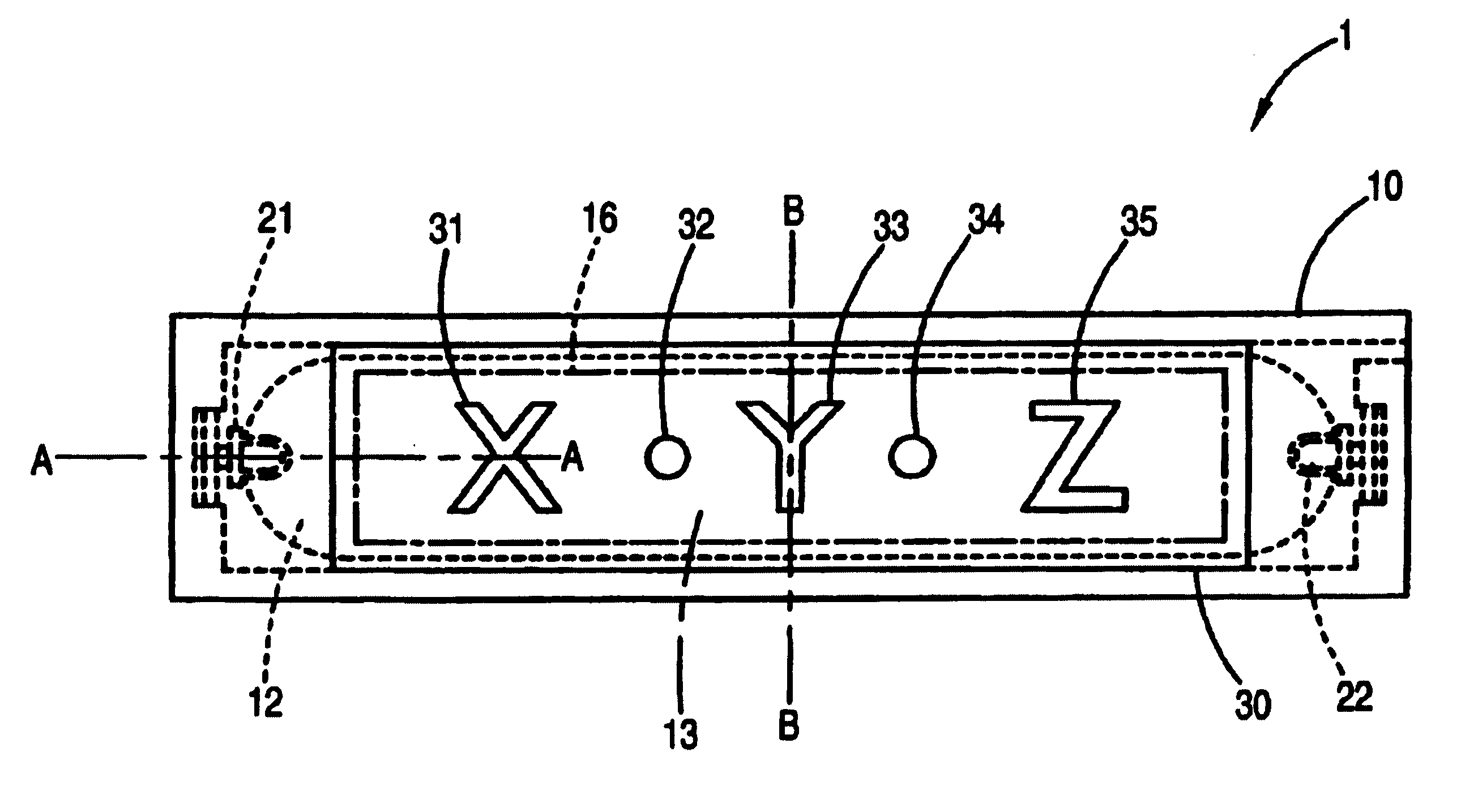
[0009]The invention is made in view of the problems and the object is to provide an illumination device in which a desired shape and a character can be displayed with uniform emission throughout an emission surface as well as with high illumination effect.
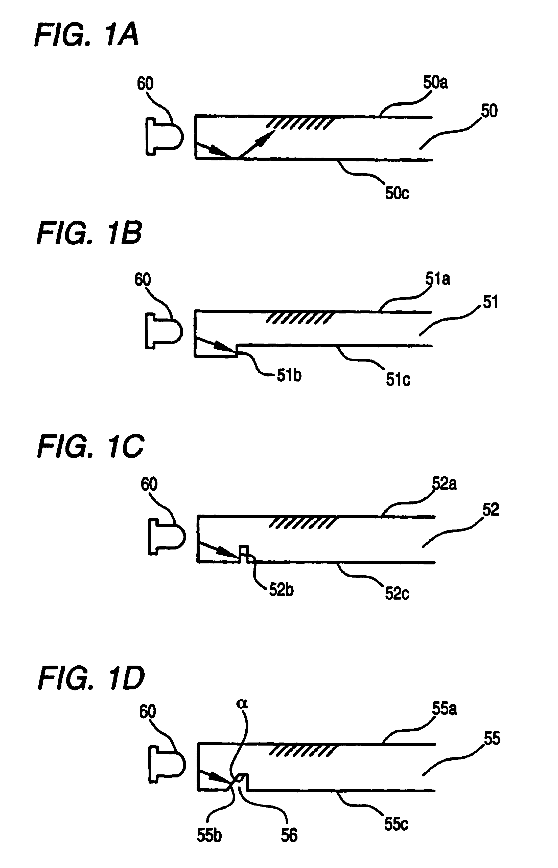
[0011]In the illumination device configured as described above, light emitted from the light source (or LED) toward the backside of the light guide member in the vicinity of the light source is shielded by the light shield surface. As a result, the light is prevented from being reflected and being radiated from the upper design surface and the radiation of light of high luminance in the vicinity of the light source is prevented. Hereby, further uniform radiation is acquired throughout the design surface. As described above, according to the configuration according to the invention, radiation from the whole design surface is unified without reducing the design surface unnecessarily. That is, the high illumination effect is acquired in the illumination device provided by the invention and further uniform light can be radiated throughout the design surface.
[0013]In such configuration, after light incident on the light guide member from the light source is reflected on the backside of the light guide member, it is radiated from the upper surface of the light guide member, that is, the emission surface, however, as the grooves are formed on the backside of the light guide member, a state of reflection at the bottom of each groove and a state of reflection on the other part of the backside of the light guide member are different and hereby, a shape of the bottom is displayed. That is, the bottom of the groove provided to the backside of the light guide member functions as a display part and if the display part is formed so that it has a desired shape, the desired shape can be displayed. As the display part formed more distantly from the light source is formed closer to the upper surface of the light guide member, distance after reflection between light reflected on the display part formed more distantly from the light source and the emission surface is shorter and the light is radiated at higher efficiency from the emission surface. Hereby, even if the light volume received by the display part which is more distant from the light source is smaller, the radiant efficiency of light is contrarily enhanced. Even the display part formed distantly from the light source can receive incident light parallel to the light source at the edge on the side of the light source. Therefore, difference in luminance between light reflected on each display part and radiated outside is reduced. That is, the luminance of each display part is unified and all the display parts can be displayed by emission more uniform.

Problems solved by technology

That is, the radiation of light was not uniform throughout the design surface.
However, in such configuration, the area of the design surface is reduced and the illumination effect is reduced.
Although a larger a light guide member with a larger emission surface is desired from a viewpoint of enhancing the design of the illumination device, a large emission surface is adopted to a illumination device with the above configuration, nonuniformity in luminance becomes remarkable and such a demand cannot be satisfied.
The problem of the nonuniformity of luminance remains unsolved after all.

Method used


Image

  • Illumination device
  • Illumination device
  • Illumination device

Examples


Embodiment Construction

[0035]Each member of the invention will be described below.

[0036]Although the type of a light source is not particularly limited, various types of LEDs such as a round type and a chip type can be adopted. As LED is small-sized, the whole light emitting device is miniaturized by using it. LED also has advantages such that only small driving power is required and power consumption is lower, as well as that the life is long. Further, as the calorific value is small, a thermal effect upon members around LED is small.

[0037]The luminescent color of the adopted LED is not particularly limited. A plurality of LEDs which have different luminescent color may be also combined. In case plural LEDs are used, the luminescence of each LED is controlled and light according to various luminescence can be emitted. For example, if red, green and blue light emitting diodes are used and a state and the quantity of tho luminescence of each LED are controlled, desired light can be omitted. The number of u...


PUM


Abstract

In the illumination device of the invention, an LED is oppose to a side surface of a flat light guide member. A light shield surface for shielding light from the LED and emitted toward the backside of the guide member in vicinity of the LED on the backside of the light guide member.

Description

CROSS REFERENCE TO RELATED APPLICATIONS[0001]The present invention is based on Japanese Patent Applications No. 2001-76902 and No. 2001-87696, the entire contents of which are incorporated herein by reference.BACKGROUND OF THE INVENTION[0002]1. Field of the Invention[0003]The present invention relates to an illumination device that radiates light from a light emitting diode (LED) via a light guide member. The illumination device according to the invention can be utilized for a display plate for a vehicle such as a scuff plate and a display plate for dwelling such as a nameplate.[0004]2. Description of Related Art[0005]For an illumination device for an automobile, a scuff plate illumination device 200 having a configuration shown in FIG. 19 is known. FIG. 19 is a longitudinal sectional view showing the scuff plate illumination device 200. The scuff plate illumination device 200 is provided with a flat light guide member 210, the LEDs 220 arranged opposite to the side 211 of the light...

Claims


Application Information

Patent Timeline
IPC IPC(8): F21V8/00G02B6/00
CPCG02B6/0018G02B6/006G02B6/0038G02B6/0061G02B6/0068Y10S362/812
Inventor INUI, SHUJIHASHIMOTO, MORIYUKIYAMANAKA, OSAMUSANO, YOSHIONAWASHIRO, MITSUHIROITO, HIROSHIMISAWA, AKIHIROKAMIYA, TAKAYUKI
Owner TOYODA GOSEI CO LTD
Learn More