
Perimeter lighting apparatus

a technology for lighting apparatus and perimeters, applied in lighting and heating apparatus, fixed installation, lighting support devices, etc., can solve the problems of bulb failure, bulb failure, and inability to cut to different lengths for different applications, so as to improve efficiency and longevity.

Inactive Publication Date: 2005-11-29
THE SLOAN COMPANY INC DBA SLOANLED
View PDF18 Cites 137 Cited by
  • Summary
  • Abstract
  • Description
  • Claims
  • Application Information

AI Technical Summary

Benefits of technology

[0012]The present invention provides an improved elongated perimeter light that uses light emitting diodes (LEDs) as its light source to take advantage of their improved efficiency and longevity. The perimeter light can be connected in series with other perimeter lights, with each of the lights capable of being cut in the field to match the length of the structural feature.
[0015]The tube of each perimeter light disperses the light from the light source array without over attenuating it, so that perimeter light provides bright light that simulates the look of straight tube neon. By being cuttable at intervals, custom sized lighting devices do not need to be ordered, reducing the lead-time and expense associated with installing perimeter lighting.
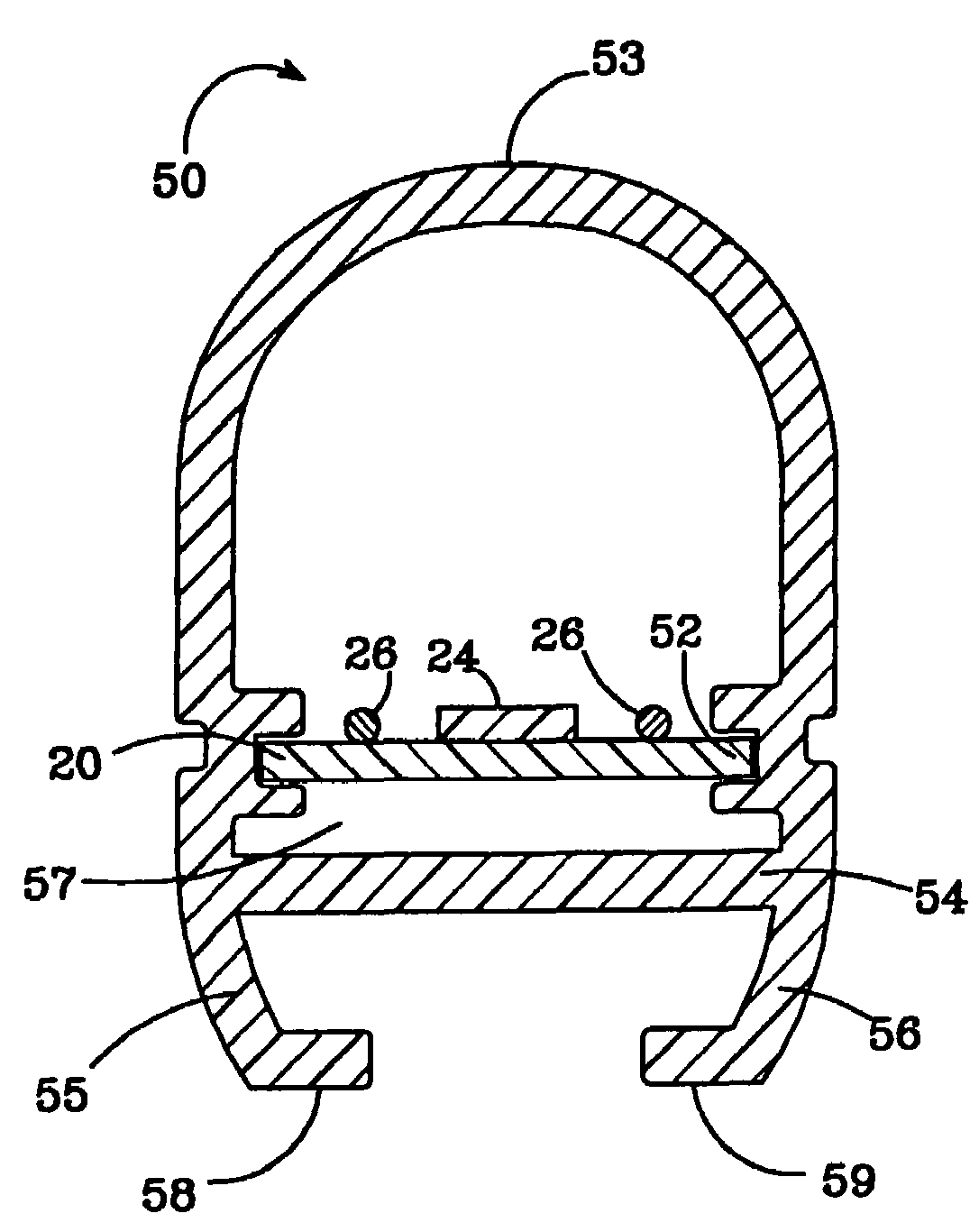
[0017]The new perimeter light also provides bumpers that fit on the open ends of each tube. The bumpers of adjacent perimeter lights rest adjacent to one another so that they can compensate for the expansion and contraction of the tubes during temperature change. They are also designed to glow and illuminate at the color of the perimeter light. Covers can be used over the junction between adjacent lights, with the covers preferably made of the same material as the tube. The combination of illumining bumpers with the cover section allows the junction to emit light similar to the perimeter light.
[0018]The new perimeter light is rugged, energy efficient and easy to install. It is 30 to 70% more efficient than neon lighting and the LEDs can last more than 5 times longer than neon bulbs. It can easily be installed as a replacement to conventional neon lighting.

Problems solved by technology

Some of the disadvantages of neon lighting is that neon bulbs have a relatively short life, are fragile and can consume a relatively large amount of power.
Also, neon bulbs can experience difficulty with cold starting, which can lead to the bulb's failure.
One disadvantage of this strip is that it cannot be cut to different lengths for different applications.
This arrangement is not durable enough to withstand the conditions for outdoor use.
The flexible tape and its adhesive can easily deteriorate when continually exposed to the elements.
This arrangement is also not durable enough to withstand the conditions for outdoor use.
One of the disadvantages of this light is that it cannot be cut to match the length of a building's structural features.
Also, the connectors between adjacent sections of lighting are bulky and result in a visible junction between the sections.
In addition, the light's tube significantly attenuates the light emitted by its LEDs, significantly reducing the light's brightness.
Further, the light does not include a mechanism for compensating for the expansion and contraction between adjacent lights.

Method used


Image

  • Perimeter lighting apparatus
  • Perimeter lighting apparatus
  • Perimeter lighting apparatus

Examples


Embodiment Construction

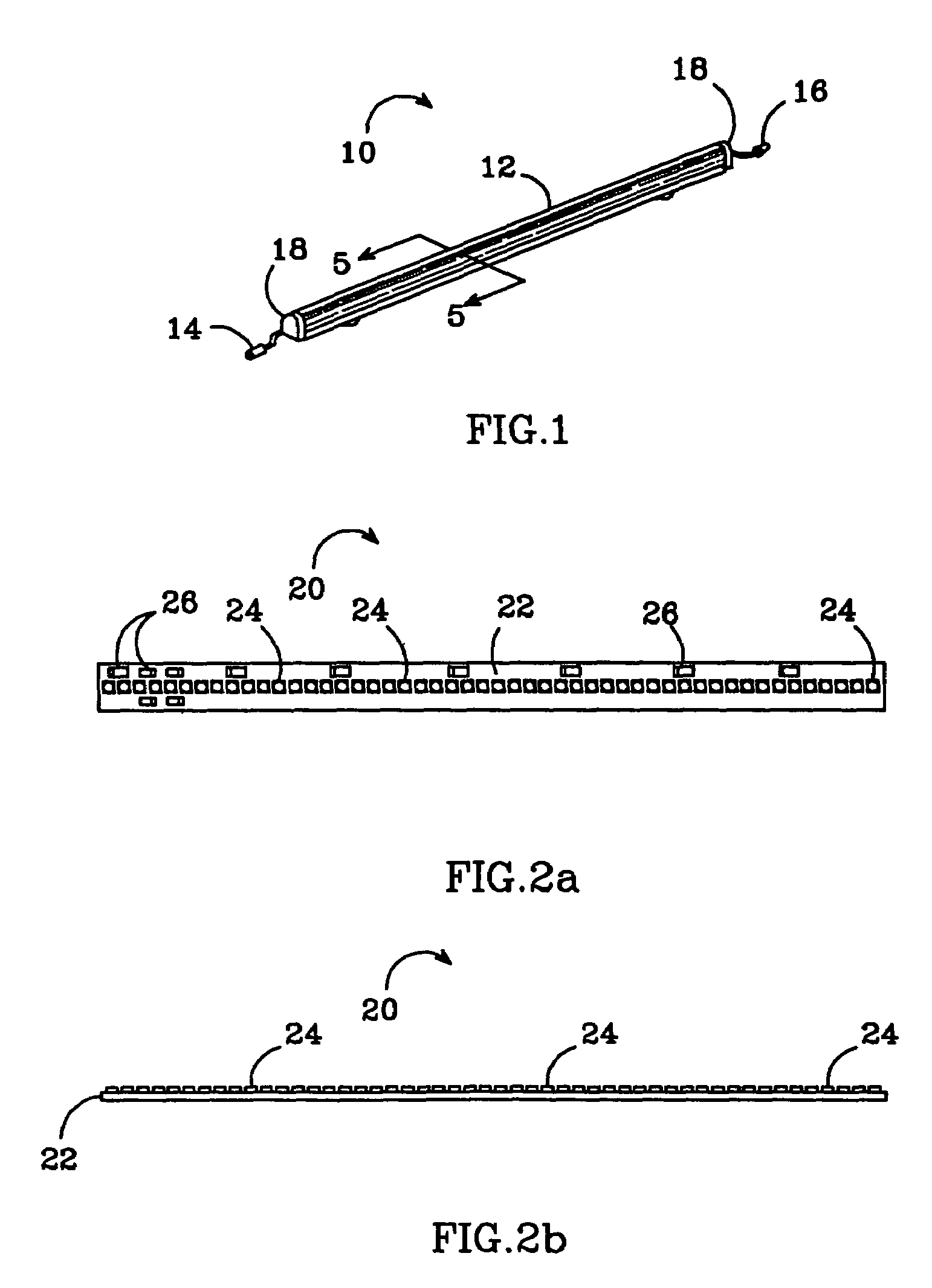
[0041]FIG. 1 shows one embodiment of a perimeter light 10 constructed in accordance with the present invention. It includes an elongated tube 12 that has a substantially oval shaped cross-section, and houses a PCB with LEDS in a linear array (shown in FIGS. 2a and 2b). The tube material should be impact resistant and UV stable with one of the preferred materials being acrylic. To provide the maximum light emission from the LEDs, the tube should have filter characteristics that transmit primarily the wavelength of light emitted from the LED array, while having the opacity to diffuse but not over-attenuate the emitting light.

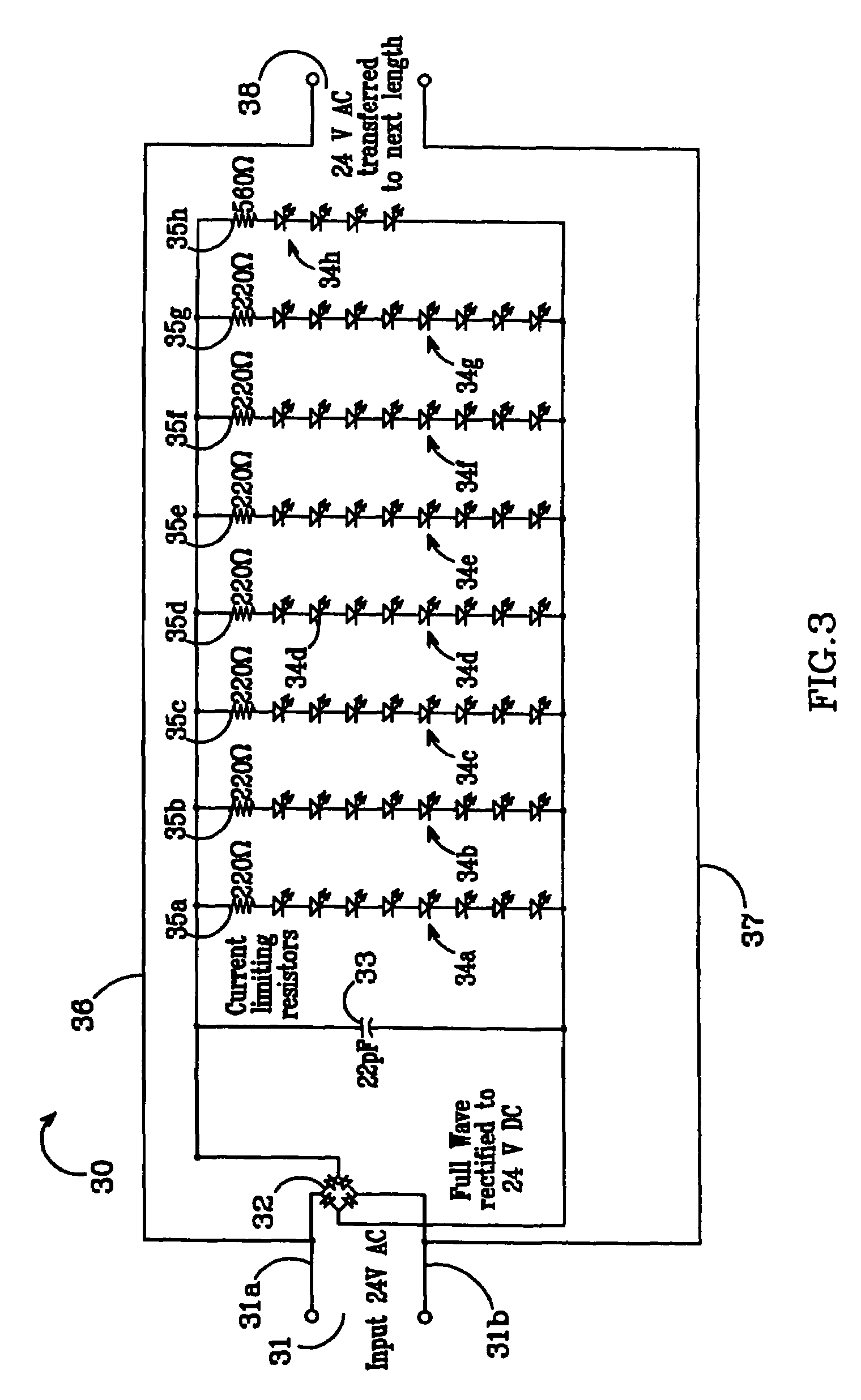
[0042]The perimeter light 10 has a male connector 14 at its first end and a female connector 16 at its second end, both arranged so that multiple lights 10 can be electrically connected in series. Other embodiments can have the connector types reversed or can use different connectors. This allows multiple lights 10 to be connected along a long or high structural f...


PUM


Abstract

An elongated perimeter light is disclosed, which comprises a linear array of light sources (LEDs) that are electrically illuminated. The array of light sources is disposed within an elongated transparent tube, with the tube transmitting and dispersing the light from the array giving the appearance that said array of light sources is a continuous light source. The array of light sources is capable of being cut at intervals down its length to shorten it. The light sources that remain in the array continue to emit light and the tube can be cut to match the length of said array. The present invention also discloses systems for lighting structural features, with one system according to the present invention comprising a plurality of elongated perimeter lights. The perimeter lights are electrically coupled in a daisy chain with the electrical power at each of the perimeter lights being transmitted to the successive light. A mechanism is included for anchoring the plurality of perimeter lights to a structure to illuminate it. Each of the perimeter lights can be cut at intervals down its length while not interfering with its ability to transmit its electrical power to successive lights.

Description

[0001]This application is a divisional of patent application Ser. No. 10 / 202,276 filed on Jul. 24, 2002, and claims priority of that application.[0002]This application claims the benefit of provisional application Ser. No. 60 / 307,820 to Sloan et al., which was filed on Jul. 25, 2001.BACKGROUND OF THE INVENTION[0003]1. Field of the Invention[0004]This invention relates to perimeter or border lighting for buildings and more particularly to perimeter or border lighting using light emitting diodes as the light source.[0005]2. Description of the Related Art[0006]Perimeter or border lights (“perimeter lighting”) are commonly used on buildings to accentuate the structure, to draw customer attention to the building, and to provide safety lighting. Most conventional perimeter lights use neon bulbs for the light source. Some of the disadvantages of neon lighting is that neon bulbs have a relatively short life, are fragile and can consume a relatively large amount of power. Also, neon bulbs ca...

Claims


Application Information

Patent Timeline
Patent Type & Authority Patents(United States)
IPC IPC(8): F21S4/00F21V15/015F21V21/005
CPCF21S4/006F21S4/007F21S8/032F21V15/015F21V21/005F21Y2101/02F21Y2103/003Y10S362/80Y10S362/806F21S4/24F21S4/26F21Y2103/10F21Y2115/10
Inventor SLOAN, THOMAS C.SLOAN, JAMES J.
Owner THE SLOAN COMPANY INC DBA SLOANLED
Learn More