Optical head apparatus, optical information recording and reproducing apparatus, method for detecting aberration and method for adjusting optical head apparatus

Inactive Publication Date: 2005-11-22
PANASONIC CORP
View PDF8 Cites 12 Cited by
  • Summary
  • Abstract
  • Description
  • Claims
  • Application Information

AI Technical Summary

Benefits of technology

[0027]According to the above-mentioned configuration, even with a high-density information storage medium, a detection signal of spherical aberration can be obtained stably and information can be recorded and reproduced stably.

Problems solved by technology

However, the increase in the numerical aperture NA leads to the increase in spherical aberration generated due to the thickness error of a substrate as a protective layer of the optical disk 107.
However, there has been no suitable method for detecting spherical aberration.
Therefore, as the density of information recorded on the information storage medium increases, the optically required condition becomes stricter, which may lead to problems in that a beam cannot be sufficiently narrowed on the information storage medium because of spherical aberration, etc. so that information cannot be recorded stably, and information cannot be reproduced stably.

Method used


Image

  • Optical head apparatus, optical information recording and reproducing apparatus, method for detecting aberration and method for adjusting optical head apparatus
  • Optical head apparatus, optical information recording and reproducing apparatus, method for detecting aberration and method for adjusting optical head apparatus
  • Optical head apparatus, optical information recording and reproducing apparatus, method for detecting aberration and method for adjusting optical head apparatus

Examples


first embodiment

(First Embodiment)

[0059]In a first embodiment of the present invention, a method of dividing a reflected light from an optical disk as an information storage medium into an inner disklike beam and an outer circumferential beam by a hologram element, and obtaining a spherical aberration error signal from a diffracted light by the hologram element and an information reproducing signal from the zero order light thereby will be mentioned.

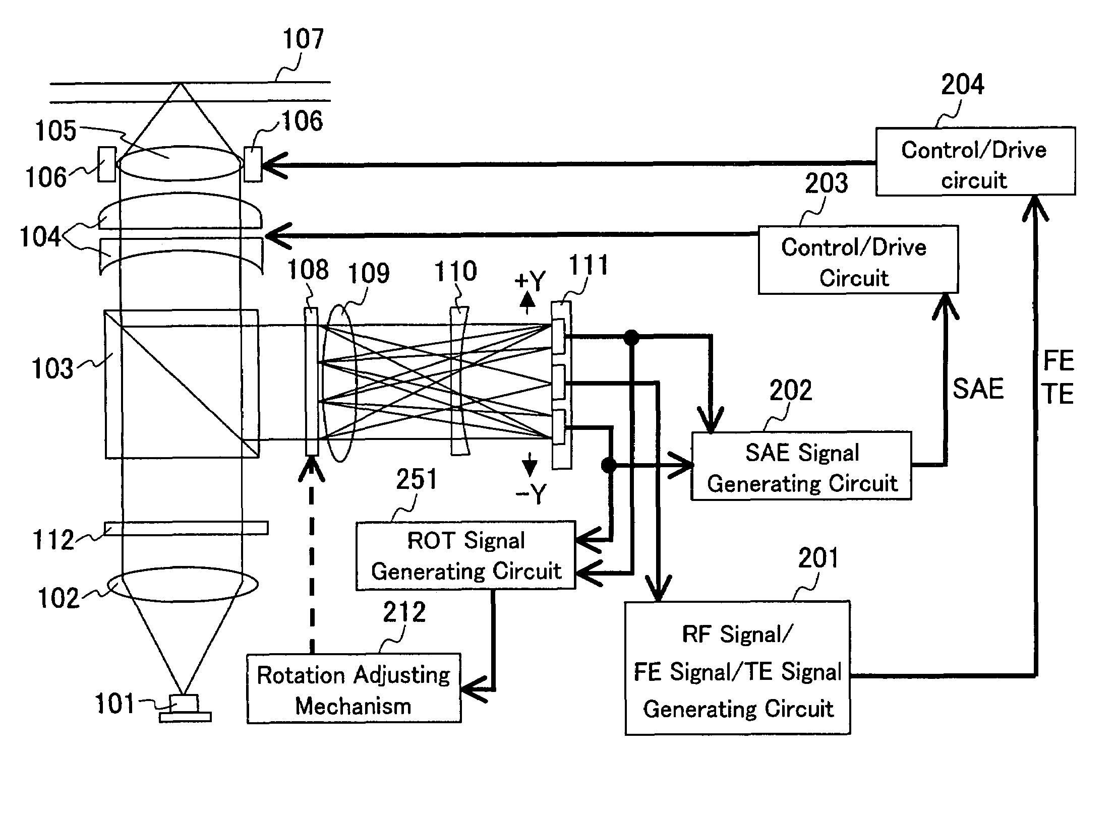
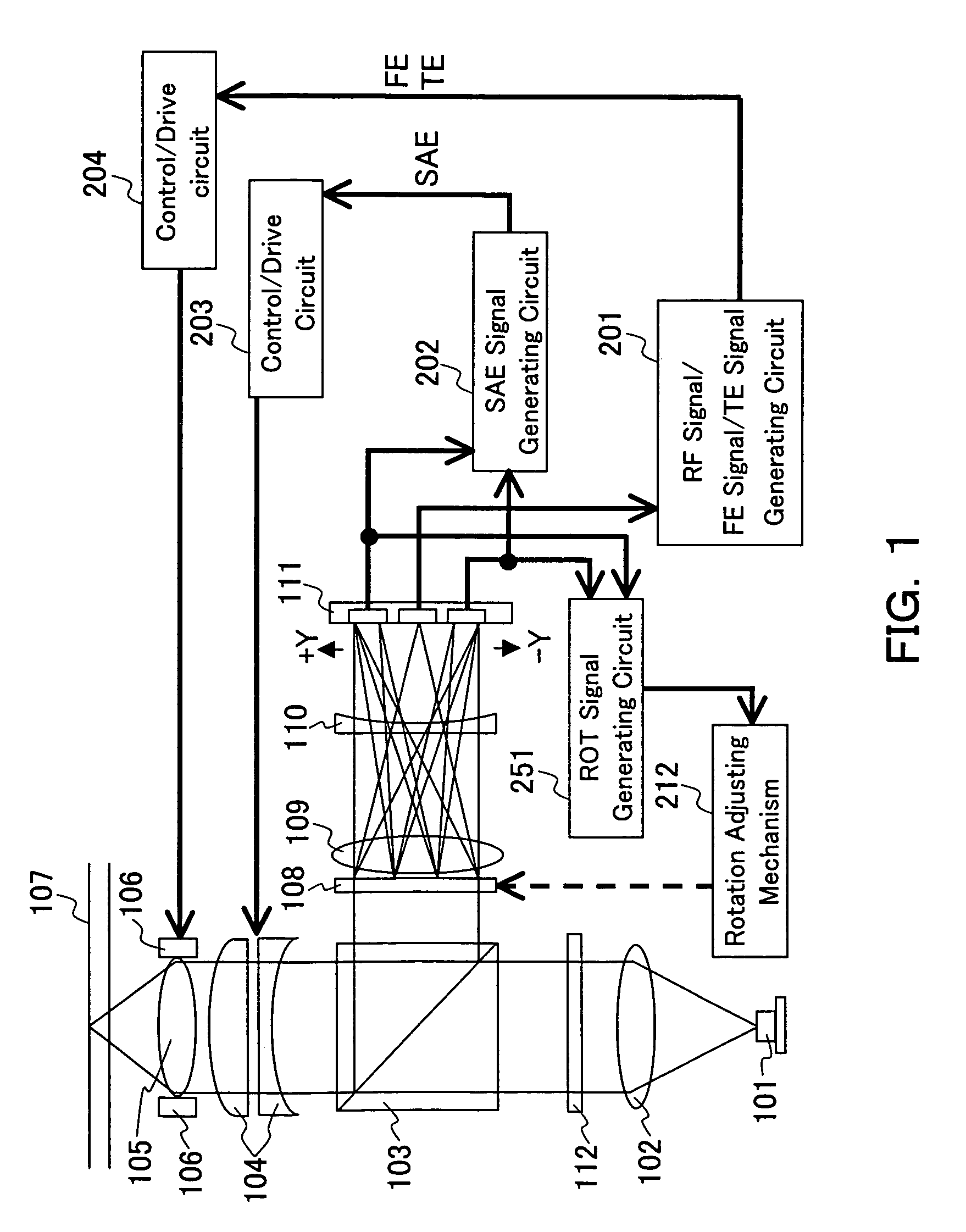
[0060]FIG. 1 is a view showing a configuration of an optical head apparatus according to the first embodiment. In FIG. 1, light emitted from a semiconductor laser 101 as a light source is converted by a collimator lens 102 into a parallel beam of light and passes through a diffraction grating 112 as a sub-beam generating means. At this time, the ±first order diffracted light is generated by the diffraction grating 112 and thus the light is divided into three beams. Among the three beams, a beam by the zero order diffracted light in the center is referre...

second embodiment

(Second Embodiment)

[0093]In a second embodiment of the present invention, a case where the hologram element as a light dividing means for dividing light to detect spherical aberration is blazed will be mentioned. FIG. 13 shows a configuration of this optical system. This configuration is substantially the same as in the configuration of the first embodiment except that another hologram element 114 is used instead of the hologram element 108 and another photodetector 115 is used instead of the photodetector 111.

[0094]A signal output from the photodetector 115 is input to two FE signal generating circuits 205 and 209. A SAE signal generating circuit 202 receives signals output from the two FE signal generating circuits 205 and 209 and calculates the difference signal therebetween, and outputs the difference signal as a spherical aberration error signal (SAE signal).

[0095]FIG. 14 is a front view showing a hologram element 114. In an outer region 1208 of a circle with a radius R1, a dif...

third embodiment

(Third Embodiment)

[0106]Next, as a third embodiment, the configuration in which light in an inner disklike region and light in an outer circumferential region are diffracted in the oblique direction is explained. FIG. 16 shows a configuration of this optical system. This configuration is substantially the same as the first embodiment except that another hologram element 116 is used instead of the hologram element 108 and another photodetector 117 is used instead of the photodetector 111.

[0107]FIG. 17 is a front view showing a hologram element 116. Light entering the outer region 1210 of the circle with a radius R1 is diffracted in the +Yo and −Yo directions. On the other hand, light entering the inner region 1211 of the circle with a radius R1 is diffracted in the +Yi and −Yi directions. A projection of the beam reflected and diffracted by the optical disk 107 and passing through the objective lens 105 is a circle with radius Rb (a circle shown by broken line in the drawing). When R...


PUM


Abstract

An optical head apparatus capable of stably obtaining a detection signal of spherical aberration even with a high density optical disk. A spherical aberration error signal is obtained by: dividing the returning light from the optical disk into a transmitted light and a diffracted light; reproducing information with the transmitted light having a larger amount of light while dividing the diffracted light having a small amount of light into two regions, i.e., region near the optical axis and a region distant from the optical axis; determining amounts of focus deviation in respective regions as focus error signals; and taking the difference signal therebetween. Thus, it is possible to detect the amount of spherical aberration with the SN ratio of the information reproducing signal kept at high level.

Description

BACKGROUND OF THE INVENTION[0001]1. Field of the Invention[0002]The present invention relates to an optical head apparatus for obtaining a spherical aberration error signal to control a spherical aberration correcting means used for recording or reproducing information with respect to an information storage medium such as an optical disk or an optical card, an information recording and reproducing apparatus for recording and reproducing information with respect to an information storage medium, a method for detecting aberration, and a method for adjusting an optical head apparatus.[0003]2. Description of the Prior Art[0004]FIG. 28 shows a configuration of an optical head apparatus of a conventional information recording and reproducing apparatus. Light emitted from a semiconductor laser 101 as a light source is converted by a collimator lens 102 into a parallel beam of light and passes through a beam splitter 103. The beam passing through the beam splitter 103 is converged by an obj...

Claims


Application Information

Patent Timeline
IPC IPC(8): G11B7/125G11B7/135G11B7/13G11B7/09
CPCG11B7/131G11B7/1378G11B7/1381G11B7/13927G11B7/0901G11B7/0908G11B7/0909
Inventor SANO, KOUSEIKADOWAKI, SHIN-ICHIKOMMA, YOSHIAKINISHINO, SEIJIYASUDA, KATSUHIKOYASUDA, AKIHIRO
Owner PANASONIC CORP
Why Eureka
Try Eureka