
On-line control of coal flow

a technology of coal flow and control, applied in the direction of gas current separation, solid separation, chemistry apparatus and processes, etc., can solve the problems of affecting unit performance, poor coal distribution balance, and reducing combustion efficiency, so as to improve combustion efficiency

Inactive Publication Date: 2005-11-22
LEVY EDWARD KENNETH +2
View PDF4 Cites 18 Cited by
  • Summary
  • Abstract
  • Description
  • Claims
  • Application Information

AI Technical Summary

Benefits of technology

[0008]Accordingly, it is the main object of the present invention to provide an improved method and apparatus for the on-line balancing and control of pulverized coal flow into the multiple pulverized coal outlet pipes of a coal pulverizer, thereby improving boiler performance by making it possible to operate the boiler with reduced pollutant levels (e.g. NOx, CO) and increased combustion efficiencies.
[0009]It is another object of the present invention to provide an improved method and apparatus for the on-line balancing and control of pulverized coal flow from the discharge turret of a coal pulverizer into multiple pulverized coal outlet pipes and onto connected fuel conduits that does not disturb any pre-existing primary air flow balance among the multiple pulverized coal outlet pipes.
[0010]It is a further object of the present invention to provide an improved method and apparatus for the on-line balancing and control of pulverized coal flow from the discharge turret a coal pulverizer into multiple pulverized coal outlet pipes, where the type of pulverizer is a pressurized vertical spindle pulverizer. It is a further object of the present invention that the apparatus can be readily installed within an existing pressurized vertical spindle pulverizer without causing a significant pressure drop.
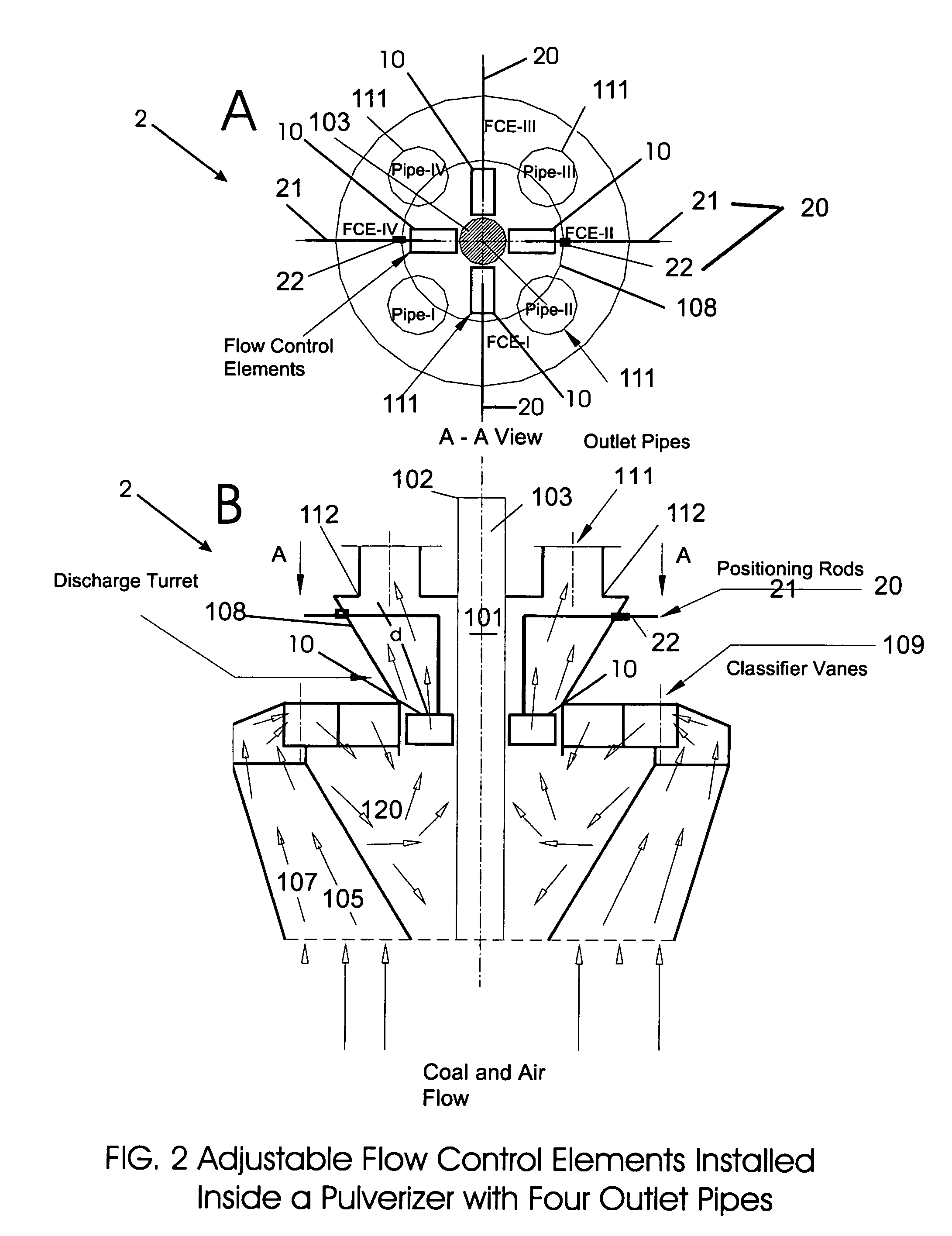
[0014]Yet another object of the present invention is to provide a means for independently adjusting the positioning of each of the multiple flow control elements within the discharge turret and thereby, controlling the flow of pulverized coal to the corresponding outlet pipe.
[0016]The method of the present invention is practiced by monitoring either the pulverized coal flow at the individual pulverized coal outlet pipes or the individual flame characteristics, and then compensating for imbalances in the coal particulate flow or differences between flame characteristics by selectively adjusting the individual flow control elements as needed, thereby balancing and controlling the distribution of pulverized coal and improving combustion efficiency.

Problems solved by technology

Poor balance of pulverized coal distribution between pulverized coal outlet pipes is commonly experienced in utility boilers.
Unbalanced distribution of coal among the pulverized coal outlet pipes adversely effects unit performance and leads to decreased combustion efficiency, increased unburned carbon in fly ash, increased potential for fuel line plugging and burner damage, increased potential for furnace slagging, and irregular heat release within the combustion chamber.

Method used


Image

  • On-line control of coal flow
  • On-line control of coal flow
  • On-line control of coal flow

Examples


Embodiment Construction

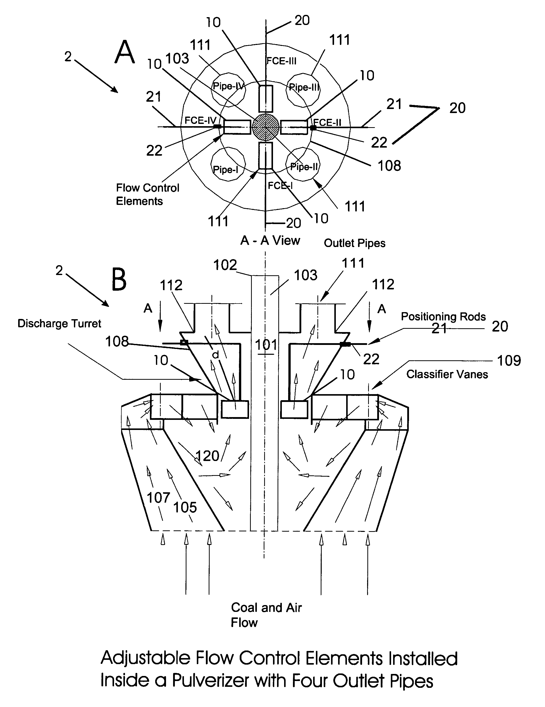
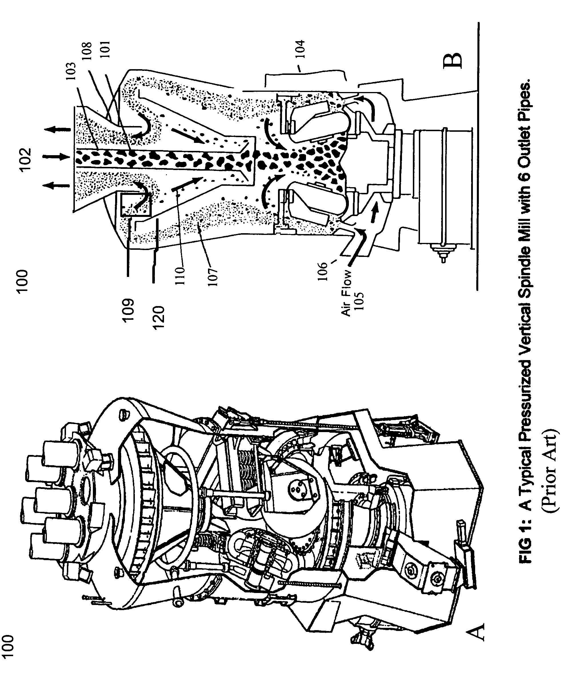
[0025]In a conventional coal pulverizer 100 (as shown in FIGS. 1A–1B and FIG. 2) raw coal 101 is dropped into coal inlet port 102 and by force of gravity falls through coal chute 103 until it reaches the grinding mechanism 104. The grinding mechanism 104 grinds the coal into fine pieces. Air 105 flows into air inlet port 106 and transports the pulverized coal 107 upwards towards the inverted cone-shaped discharge turret 108. Typically, the pulverized coal 107 passes through a classifier vane mechanism 109 that establishes a swirling flow within the rejects cone 120. The centrifugal force field set up in the reject cone 120 prevents coarse pieces of coal110 from entering the discharge turret 108. The coarse pieces of coal 110 fall by force of gravity back into the grinding mechanism 104. Once the pulverized coal 107 enters the discharge turret 108 it is distributed between the multiple equal diameter pulverized coal outlet pipes 111 (FIG. 1 indicates six pulverized coal outlet pipes ...


PUM


Abstract

A system for balancing and controlling the distribution of pulverized coal into multiple equal diameter outlet pipes of coal pulverizers for improving boiler performance. The device includes a plurality of flow control elements, one flow control element for each outlet pipe, all positioned a pre-determined distance upstream of the outlet pipes. Each flow control element is mounted on an independent adjustment mechanism and is thereby adjustable in position relative its corresponding outlet pipe to selectively vary the wake of the downstream coal particulate flow relative to primary air flow. The method of the present invention is practiced by monitoring coal particulate flow at the outlet pipes relative to primary air flow or individual flame characteristics, and then compensating for noted imbalances by selectively adjusting the flow control elements, thereby balancing and controlling the distribution of coal and improving combustion efficiency.

Description

CROSS-REFERENCE TO RELATED APPLICATIONS[0001]The present application derives priority from U.S. Provisional Patent Application No. 60 / 436,241 for “ON-LINE CONTROL OF COAL FLOW IN PRESSURIZED VERTICAL SPINDLE MILLS” filed by Levy et al. on Dec. 23, 2002.BACKGROUND OF THE INVENTION[0002]1. Field of the Invention[0003]The present invention relates to coal pulverizers and, more particularly, to the on-line control of the distribution of coal among the pulverized coal outlet pipes in pulverizers using independently adjustable flow control elements installed inside the pulverizer upstream of the entrance to each pulverized coal outlet pipe.[0004]2. Description of the Background[0005]Coal fired boilers utilize pulverizers to grind coal to a desired fineness so that it may be used as fuel for the boilers. Typically, raw coal is fed through a central coal inlet at the top of the pulverizer and falls by gravity to the grinding area. Once ground (different types of pulverizers use different gr...

Claims


Application Information

Patent Timeline
IPC IPC(8): B02C15/00B07B7/08B07B7/00
CPCB02C15/00B07B7/08B02C2015/002
Inventor LEVY, EDWARD KENNETHBILIRGEN, HARUNALI, ELSHABASI
Owner LEVY EDWARD KENNETH
Learn More