
Thermal protection of an article by a protective coating having a mixture of quasicrystalline and non-quasicrystalline phases

a protective coating and quasi-crystalline technology, applied in the field of aircraft gas turbines, can solve the problems of low thermal conductivity and non-reduction effect of thermal protective coatings, and achieve the effect of reducing potential damage and good protection of substrates against oxidation

Inactive Publication Date: 2005-11-15
GENERAL ELECTRIC CO
View PDF17 Cites 20 Cited by
  • Summary
  • Abstract
  • Description
  • Claims
  • Application Information

AI Technical Summary

Benefits of technology

[0007]The present approach provides an article protected against heat and a method for its preparation and use. The thermally protective coating is optimized for use on a substrate such as those found in applications in the gas-turbine section of gas turbine engines. The protective coating is tailored to minimize potential damage from mechanisms such as thermal-cycling strains and stresses, while achieving good protection of the substrate against oxidation and corrosion damage.
[0008]The thermally protective coating also has a low thermal conductivity due to the presence of a substantial amount of the low-thermal-conductivity quasicrystalline phase. This low thermal conductivity of the protective coating helps to insulate the substrate. Conventional high-aluminum protective coatings typically have a thermal conductivity that is 2-5 times greater than that of the nickel-base superalloy substrates that they protect. Accordingly, they do not serve to reduce heat flow to the substrate from the hot gases of the environment. In the present case, the thermal conductivity of the composite protective coating is substantially lower, resulting in reduced heat flow to the substrate.
[0011]The substrate is typically a nickel-base alloy or superalloy having aluminum and other elements therein. The quasicrystalline phase may be of any operable type, with examples being an alloy comprising iron, copper, and aluminum; an alloy comprising iron, cobalt, chromium, and aluminum; an alloy comprising nickel, cobalt, chromium, and aluminum; an alloy comprising titanium, zirconium, nickel, and silicon; and an alloy comprising titanium, nickel, and zirconium. The non-quasicrystalline metallic phase contains nickel and aluminum. In one embodiment, the non-quasicrystalline metallic phase is the same material as the substrate or with a closely similar composition, and typically with a relatively low aluminum content in the range of about 3-8 weight percent. In another embodiment, the non-quasicrystalline metallic phase has a higher aluminum content, typically from about 15 to about 35 weight percent, and more preferably from about 15 to about 30 weight percent, to provide a transition between the substrate and the quasicrystalline metallic phase while having excellent oxidation and corrosion resistance due to the formation of an aluminum oxide scale at exposed surfaces.
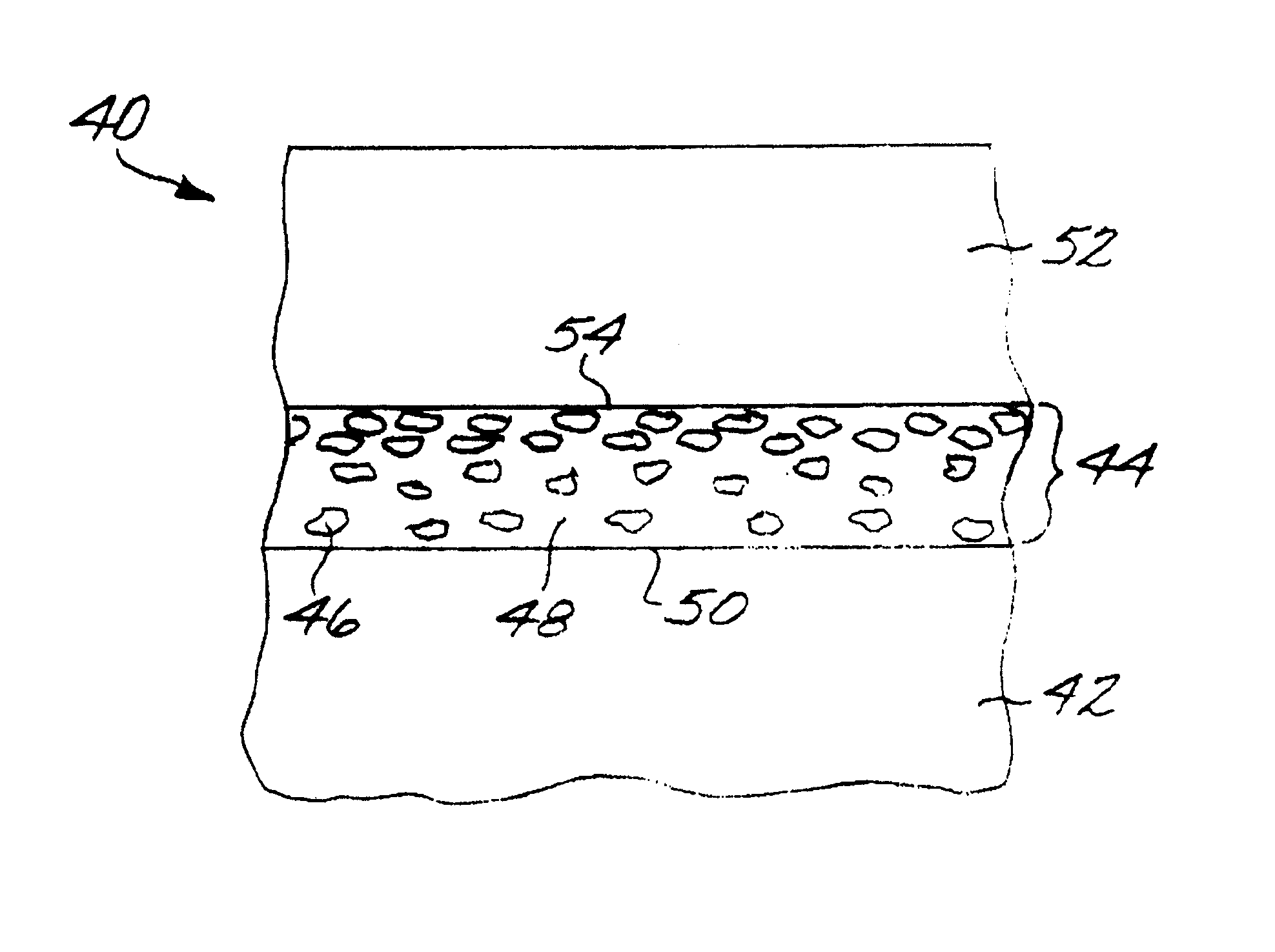
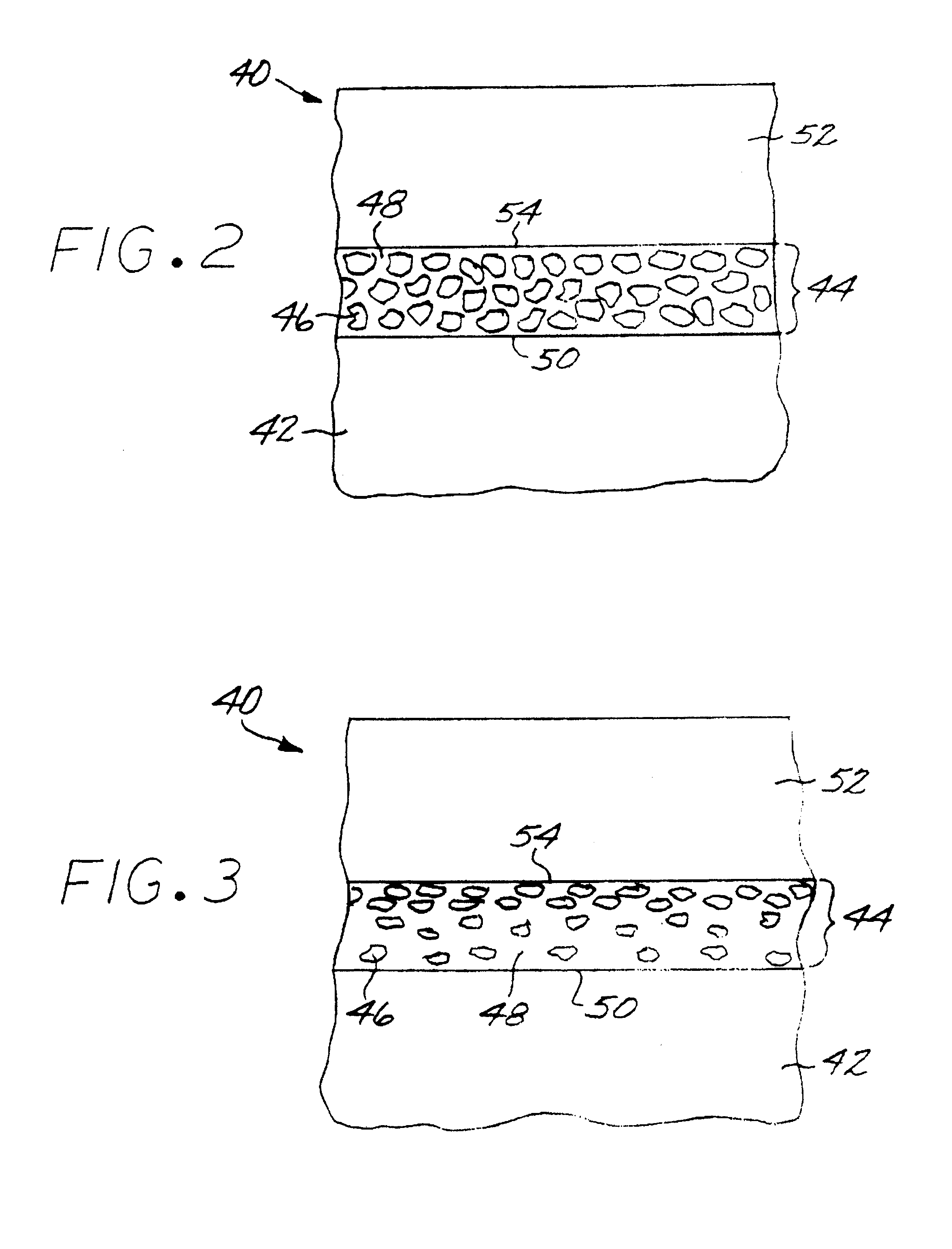
[0013]In one embodiment, the protective coating is a graded protective coating. There is a higher volume fraction of the non-quasicrystalline metallic phase adjacent to the surface of the substrate, and a lower volume fraction of the non-quasicrystalline metallic phase remote from the surface of the substrate. This embodiment provides better matching of properties, including the respective coefficients of thermal expansion, of the coating to the substrate at their interface than would a coating with the same properties throughout. Yet the greatest oxidation-resistance and corrosion-resistance properties of the quasicrystalline material are presented at the surface of the protective coating.
[0014]In any of these embodiments, the protective coating may be used as a bond coat for an overlying ceramic thermal barrier coating. Thus, there is a ceramic thermal barrier coating overlying and contacting a surface of the protective coating remote from the substrate. The ceramic thermal barrier coating provides additional thermal insulation and protection for the substrate.

Problems solved by technology

The thermally protective coating also has a low thermal conductivity due to the presence of a substantial amount of the low-thermal-conductivity quasicrystalline phase.
Accordingly, they do not serve to reduce heat flow to the substrate from the hot gases of the environment.

Method used


Image

  • Thermal protection of an article by a protective coating having a mixture of quasicrystalline and non-quasicrystalline phases
  • Thermal protection of an article by a protective coating having a mixture of quasicrystalline and non-quasicrystalline phases
  • Thermal protection of an article by a protective coating having a mixture of quasicrystalline and non-quasicrystalline phases

Examples


Embodiment Construction

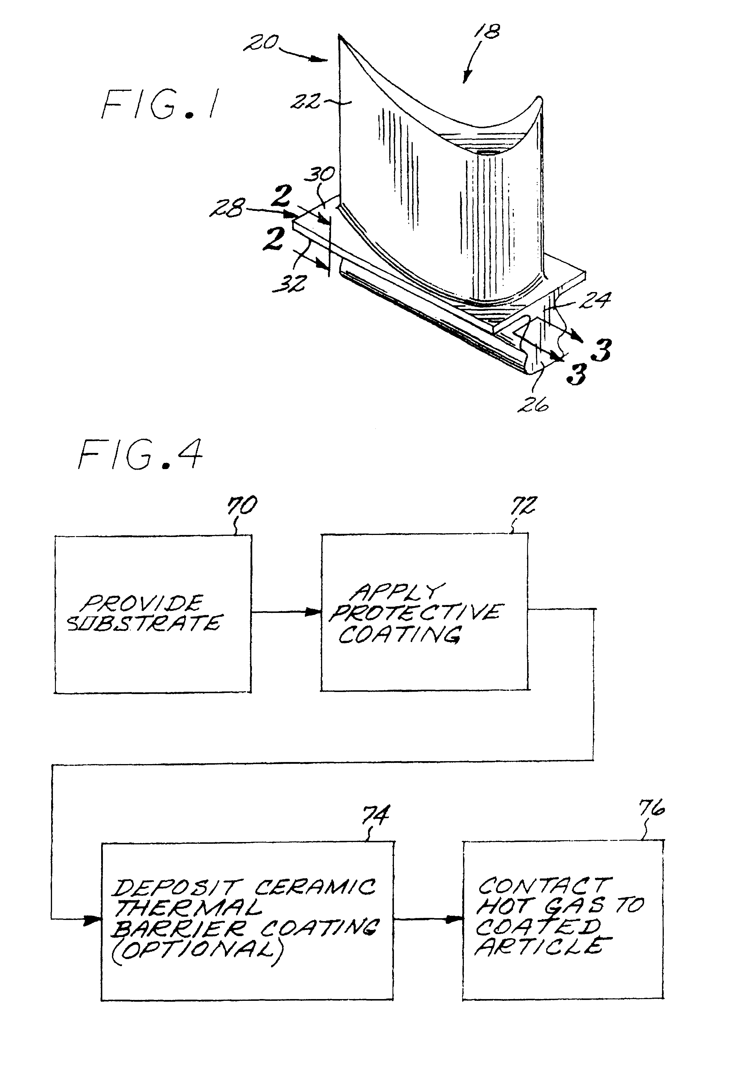
[0022]FIG. 1 depicts a component 18 of a gas turbine engine, and specifically a gas turbine blade 20. The use of the present invention extends to other applications as well, for example other components of gas turbine engines such as gas turbine vanes as well as with other articles. The gas turbine blade 20 has an airfoil 22 against which a flow of hot combustion gas impinges during service operation, a downwardly extending shank 24, and an attachment in the form of a dovetail 26 which attaches the gas turbine blade 20 to a gas turbine disk (not shown) of the gas turbine engine. A platform 28 extends transversely outwardly at a location between the airfoil 22 and the shank 24 and dovetail 26. The platform 28 has a top surface 30 adjacent to the airfoil 22, and a bottom surface 32 (sometimes termed an “underside” of the platform) adjacent to the shank 24 and the dovetail 26.

[0023]The entire gas turbine blade 20 is preferably made of a nickel-base alloy that also contains aluminum and...


PUM

PropertyMeasurementUnit
Percent by massaaaaaaaaaa
Thicknessaaaaaaaaaa

Abstract

A coated article includes formed of an alloy having a composition including nickel and aluminum, and a protective coating overlying and contacting the substrate. The protective coating is a mixture of a quasicrystalline metallic phase, and a non-quasicrystalline metallic phase comprising nickel and aluminum. The aluminum is present in an amount of from about 3 to about 35 percent by weight of the non-quasicrystalline metallic phase.

Description

[0001]This invention relates to the thermal protection of substrates against external heating and, more particularly, to the use of a mixed quasicrystalline and non-quasicrystalline protective coating to provide that protection.BACKGROUND OF THE INVENTION[0002]In an aircraft gas turbine (jet) engine, air is drawn into the front of the engine, compressed by a shaft-mounted compressor, and mixed with fuel. The mixture is combusted, and the resulting hot combustion gases are passed through a turbine mounted on the same shaft. The flow of gas turns the turbine by contacting an airfoil portion of the turbine blade, which turns the shaft and provides power to the compressor. The hot exhaust gases flow from the back of the engine, driving it and the aircraft forward. There may additionally be a bypass fan that forces air around the center core of the engine, driven by a shaft extending from the turbine section.[0003]The turbine section of the engine is heated to high temperatures by the ho...

Claims


Application Information

Patent Timeline
IPC IPC(8): B32B15/04C22C21/00F03B3/12F03B3/00
CPCC22C21/00C23C4/18C23C26/00C23C30/00F01D5/288C23C4/02Y10T428/12937Y02T50/67Y02T50/672F05D2230/31F05D2230/312F05D2230/313F05D2230/314F05D2300/605Y10T428/12764Y10T428/12611Y10T428/12944Y10T428/12736Y10T428/12931Y10T428/12458Y02T50/60
Inventor DAROLIA, RAMGOPAL
Owner GENERAL ELECTRIC CO
Learn More