
Polymerization reactor and process

a technology of polymerization reactor and process, which is applied in the direction of chemical/physical/physical-chemical processes, instruments, and fluid pressure control, etc., can solve the problems of affecting the mechanical properties of the resulting polymer, requiring a fair amount of maintenance, and being subject to potential breakdown of some moving parts, so as to prolong the process and thus the cost of the process. , the effect of increasing the cost of the process

Inactive Publication Date: 2005-11-15
DOW CORNING SA
View PDF36 Cites 7 Cited by
  • Summary
  • Abstract
  • Description
  • Claims
  • Application Information

AI Technical Summary

Benefits of technology

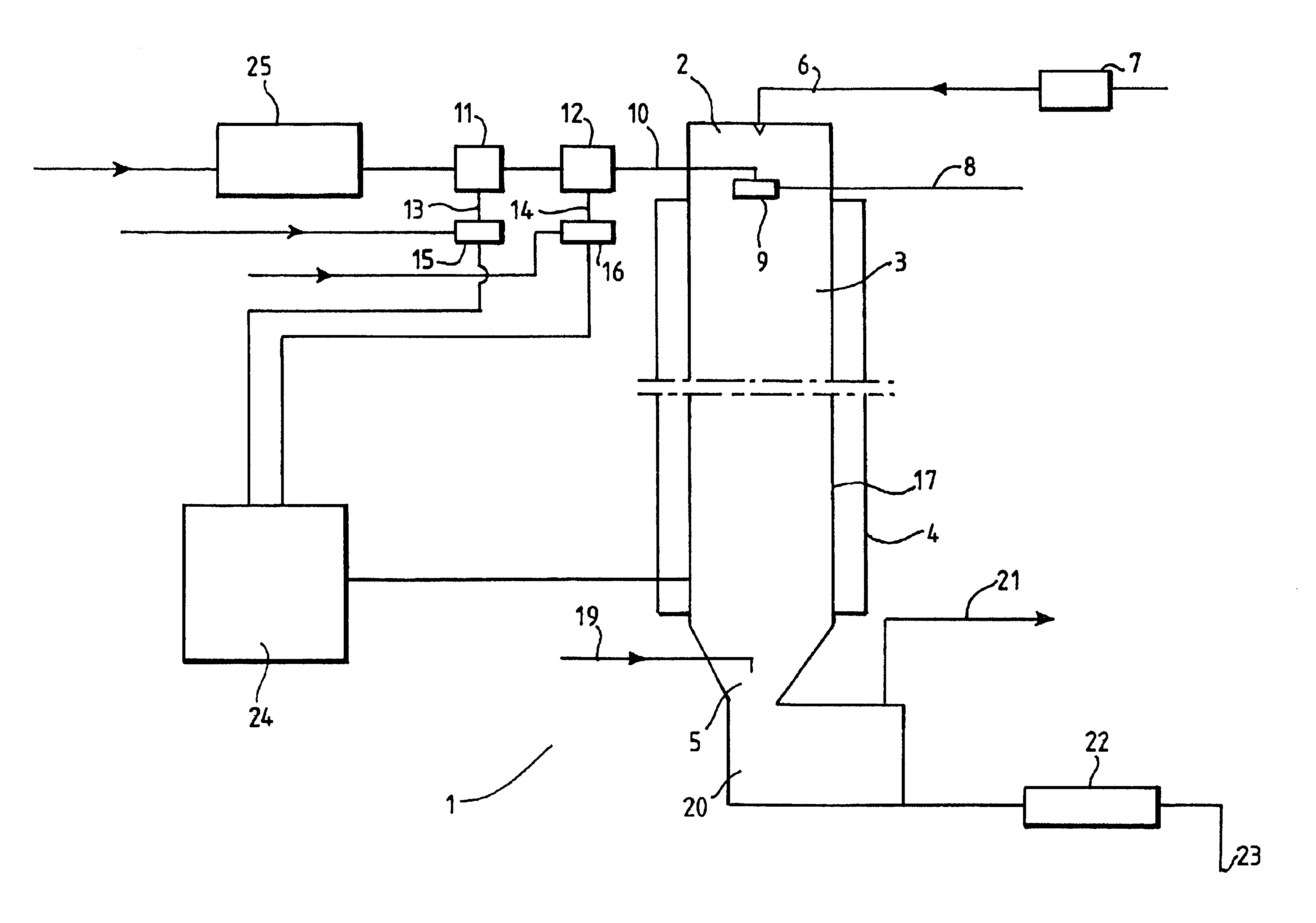
[0018]In a preferred embodiment the reaction mixture is mixed with a pressurised gas in the inlet means, the gas being used to force the reaction mixture / polymer through the reaction chamber of the reactor. This pressurised gas may be any suitable gas, eg air or nitrogen. In this preferred embodiment the mixing of the gas with the reaction mixture is effected in a way which will cause the reaction mixture to reach a foam-like consistency. In this way a large air liquid interface is created, making the system especially useful for condensation based polymerisation reactions.
[0020]The reaction chamber is elongate and preferably has a circular cross-section. Substantially cylindrical reaction chambers are easier to manufacture than reaction chambers with other cross-sections and have a preferred geometry for good mixing and elimination of dead space. Most preferably the reaction chamber is an elongate tube, which is substantially straight, coiled, helical or of any other suitable shape. A coiled or helical reaction chamber has the advantage of reducing the required overall length or height of the reactor. The term elongate, is intended to mean that the length of the reaction chamber in the direction of flow of the reaction mixture / polymer is at least twice the diameter of the reaction chamber at its widest point. Preferably the internal diameter of the reaction chamber is from 2 to 25 cm, more preferably from 5 to 10 cm. Larger diameters are also possible, but will only be efficient if sufficient reaction mixture is provided to cause sufficient flow in the reactor to ensure efficient mixing and heat transfer in the reaction mixture / polymer. Adequate flow rates for large diameter reaction chambers would be impracticable in most cases. A preferable length of reaction chamber would be from 25 cm to 50 meters, more preferably 20 to 40 m in length. The reaction chamber may have a porous wall of the type described in European patent application No 0522776, but is preferably non-porous, for example it may be made from a carbonised steel.
[0027]The control means may be any appropriate controlling system able to control polymer being made in a reaction unit in accordance with this invention. The control means may control the input of one or more viscosity controlling agents but preferably is adapted to control the input of one viscosity controlling agent at any one time. In particular the control means may be a computer based system, able to monitor pressure drop in the reaction chamber by, receiving pressure drop information from a pressure detecting means and being programmed such that it is able to translate the received information into a form which allows it to calculate a compensating flow rate of viscosity controlling agent and transmit a signal detailing the result of the calculation in a form suitable to cause the means for introducing each viscosity controlling agent into a premixer to initiate the compensating flow rate.
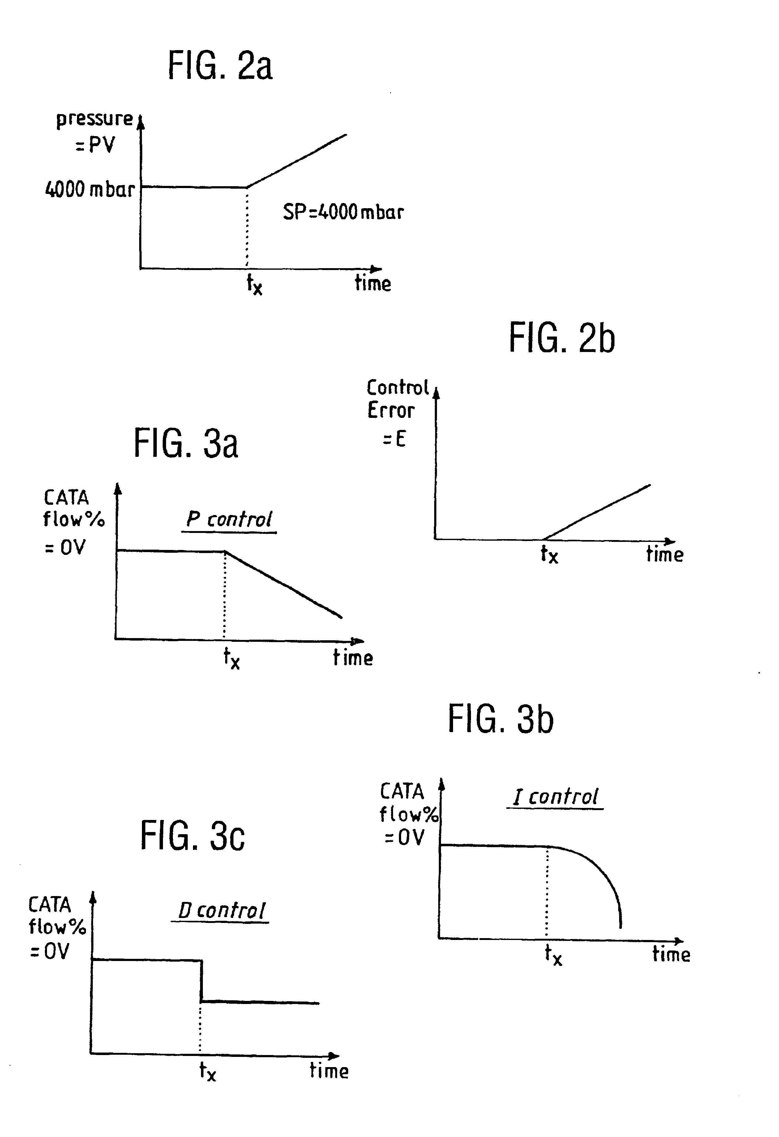
[0039]The Integral control function is a control of the velocity at which the catalyst flow is changed. Hence, if for instance the value of E doubles, the catalyst flow will be adjusted twice as fast. The Integral function is mainly required for very fast processes. It can for example control the action of the control means so as to avoid “over”-reaction to a control error. The Integral control function may also eliminate permanent control errors, for example, in the event that E was varying with time in a wave form, ie a purely proportional action there would occur a permanent control error because of the delay between the change in catalyst flow and the impact on the pressure drop and Integral control would eliminate such an error. Integral control for condensation polymerisation systems is derived from equations 2 and 3 below: δ⁡(OV)δ⁢ ⁢t=100PB×TI×(SP-PV)=100PB×TI×E(2)or after integration with time OV=100PB*TI⁢∫0t⁢(SP-PV)· ⁢ⅆt(3)TI is a constant which henceforth will be referred to as integral time.
[0041]Each of the above three control functions may be an important consideration for the overall control of the relationship between E and OV and the overall control of the relationship requires an input of all three control functions in accordance with the following relationship OV=100PB⁡[(SP-PV)+1TI⁢∫0t⁢(SP-PV)* ⁢ⅆt-TD*ⅆPVⅆt](6)The parameters of the control means which need to be tuned are PB, TI, and TD. By determining these values, one can control the viscosity of the resulting polymer leaving the reaction chamber outlet means.

Problems solved by technology

Dynamic reactors require a fair amount of maintenance and are subject to potential breakdown of some of the moving parts.
Mixing steps of this kind result in a reaction product with a wide molecular weight distribution, a feature known, in some instances, to adversely affect the mechanical properties of the resulting polymer.
Furthermore the use of an additional step leads to a longer and therefore typically more expensive process.
However, this means there is a significant period of dead time between determination of the viscosity and recirculation of sample and therefore a potentially major portion of reaction product with an incorrect viscosity will be released from the reaction chamber prior to commencement of recirculation and any change of reaction conditions or the like.

Method used


Image

  • Polymerization reactor and process
  • Polymerization reactor and process
  • Polymerization reactor and process

Examples


example 1

[0071]This example describes the polycondensation of OH end-blocked polydimethylsiloxane polymer with a viscosity of 330000 mm2 / s. (Target Range 300000 to 360000 mm2 / s) using a reactor having a helical coil of 50 mm internal diameter and a length of approximately 25 m.

[0072]Low viscosity linear silanol monomers and / or oligomers (viscosity 70 mm2 / s) were fed along the supply means to the inlet means at a controlled rate of 450 kg / hour. The monomers and / or oligomers were heated and recirculated in a heat exchanger prior to introduction into a premixer for mixing with catalyst. The required temperature was, 155° C.

[0073]The air used to force the reaction mixture / polymer through the reaction chamber was heated to a temperature of 200° C. in a heat exchanger prior to introduction in to the reaction chamber. Once both the required reaction mixture and air temperatures are reached catalyst was introduced into the monomers and / or oligomers stream. The catalyst, a phosphonitrile chloride was...

example 2

[0077]Production of trimethyl end-blocked polymer with a viscosity of 60,000 (range 57,000 to 63,000) using a 25 meters long reaction chamber having an internal diameter of 50 mm.

[0078]In this example the rate of catalyst introduction was maintained at a constant rate and the viscosity controlling agent relied upon to compensate for pressure drop changes was the end-blocker, a trimethyl siloxane end-blocked polydimethylsiloxane with a viscosity of 50 mm2 / s. The initial flow rate of end-blocker into the monomers and / or oligomers was ˜10 kg / hour. In this case both condensation and rearrangement reactions were taking place and so if the pressure drop were to increase the viscosity would increase and it would be necessary to increase the amount of end-blocker in the system. The process undertaken was basically the same as described in example 1 although the reaction mixture / polymer flow rate was 250 kg / hour at a temperature of 170° C., the air flow rate was 250 Nm3 / hour at 200° C. The c...


PUM

PropertyMeasurementUnit
Temperatureaaaaaaaaaa
Lengthaaaaaaaaaa

Abstract

A continuous static polymerization reactor unit for the production of liquid polymers, in particular high viscosity organopolysiloxanes, in a predetermined viscosity range comprises a reactor (1) a supply means (10,25) for supplying monomers and / or oligomers to an inlet means (2), and an outlet means (5). The inlet means (2) is adapted for the introduction of a reaction mixture into a reaction chamber (3), and a means for introducing at least one viscosity controlling agent into the supply means is provided to form a reaction mixture with monomers and / or oligomers (11,13,15,12,14,16). The unit is adapted to maintain the values of temperature and flow rate of the resulting reaction mixture / polymer in the reaction chamber (3) substantially constant. A control means (24) is used to detect any variation from a predetermined pressure drop value between the inlet means (2) and the outlet means (5), and should such a variation occur the control means (24) is also used to compute and control a compensating rate of introduction of one or more of the at least one viscosity controlling agents to cause the pressure drop between the inlet means (2) and the outlet means (5) to revert to the predetermined value. A process for making liquid polymers within a predetermined viscosity range is also disclosed.

Description

FIELD OF THE INVENTION[0001]This invention relates to a polymerisation reactor for making liquid polymer and a means of controlling the viscosity of liquid polymer prepared in the reactor. It is particularly related to static reactors, more specifically to static reactors which are useful in the polymerisation of monomers and / or oligomers, by for example condensation reactions. The invention also relates to a process of making liquid polymers.BACKGROUND OF THE INVENTION[0002]Polymerisation reactors have been used for a variety of polymerisation processes. Reactors may be suitable for batch processes or continuous processes. The present invention is concerned with the latter type. Most currently available continuous polymerisation reactors are dynamic systems having some moving parts which effect the mixing of reagents and, where necessary catalyst, and which force a reaction mixture through the reactor. Dynamic reactors require a fair amount of maintenance and are subject to potenti...

Claims


Application Information

Patent Timeline
IPC IPC(8): B01J19/00B01J14/00C08G77/06C08G77/00C08G85/00C08F2/01
CPCB01J14/00B01J19/0033C08G77/06B01J2219/00033B01J2219/00094B01J2219/00162B01J2219/00164B01J2219/00168C08F2/01
Inventor GILSON, JEAN MARC
Owner DOW CORNING SA
Learn More