Eureka AIR delivers breakthrough ideas for toughest innovation challenges, trusted by R&D personnel around the world.

Dynamically configurable processor

a dynamic configurable and processor technology, applied in the field of data processors, can solve the problems of high silicon overhead, inability to quickly and cost-effectively make changes, and disadvantages in cost-sensitive applications, so as to improve the efficiency of resource use and functionality, reduce or eliminate the consideration of asic development time-table and scheduling

Inactive Publication Date: 2005-10-25
HTC CORP
View PDF16 Cites 26 Cited by
  • Summary
  • Abstract
  • Description
  • Claims
  • Application Information

AI Technical Summary

Benefits of technology

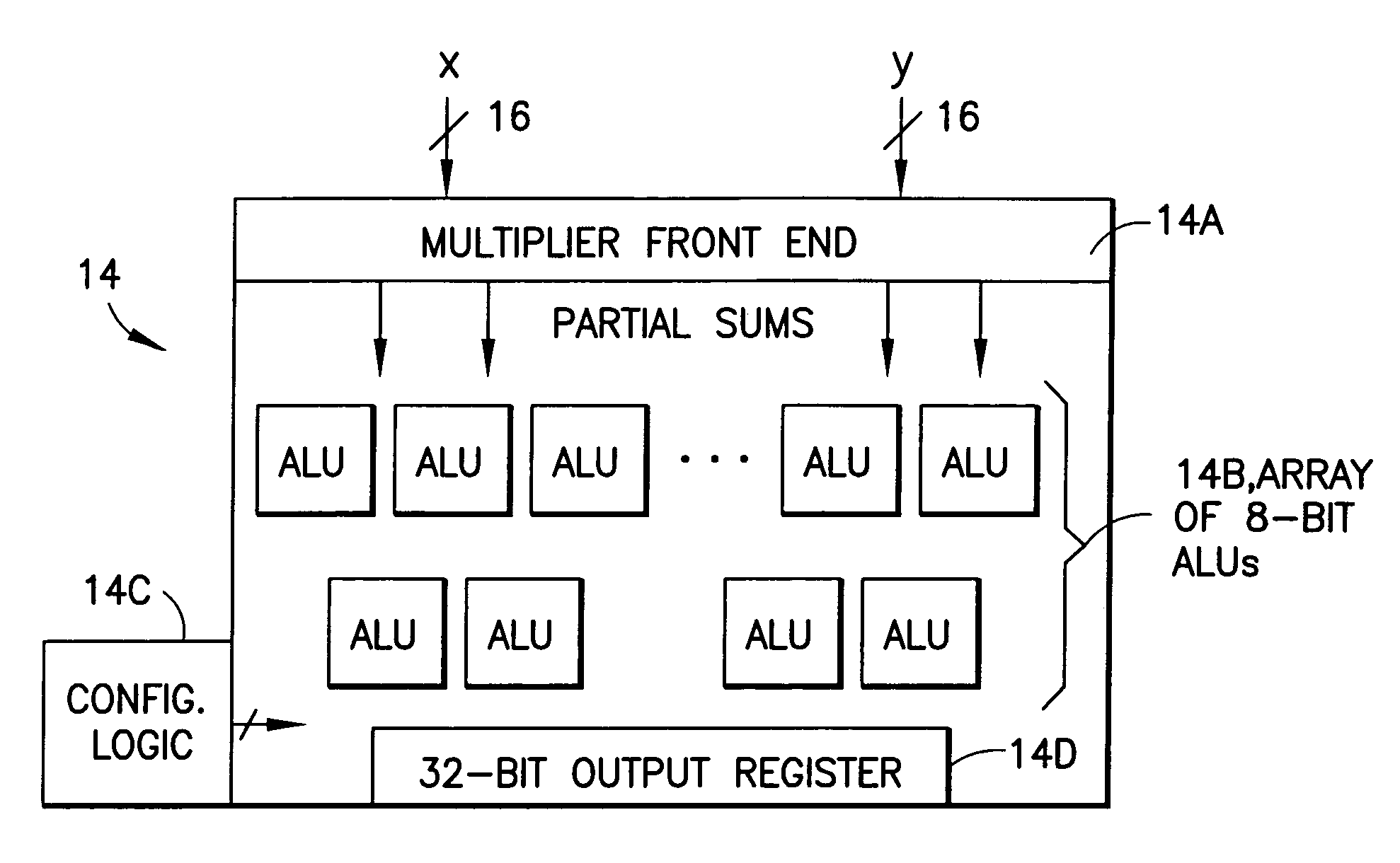
The invention is a data processor that includes a multiplier and a plurality of programmable or switchable input / output (IO) units. The processor can perform multiplication or arithmetic and logical operations on data. The processor has a configurable width for the input operands and the output operands, and can include the same or additional units for changing the sign of the input operands. The processor can be used in a wireless terminal or other applications. The technical effects of the invention include improved performance and flexibility in data processing.

Problems solved by technology

However, the ASIC approach generally requires significant design and manufacturing lead times. Furthermore, once the design(s) are committed to circuits subsequent changes become difficult or impossible to make in a rapid and cost-effective manner.
While the fine-grained nature of the FPGA makes it flexible and programmable, this is achieved at the cost of high silicon overhead, which can be a disadvantage in cost-sensitive applications.
One drawback to the use of DSPs is that most are designed to provide an overall functionality that is applicable to a number of different types of applications.
Because of this generality, no one specific DSP may be ideally suited for a specific application.
For example, a DSP that is designed so as to serve both the audio reproduction and the motor control markets may not be ideally suited for use by either, requiring some tradeoffs in performance and ease of use.

Method used


Image

  • Dynamically configurable processor
  • Dynamically configurable processor
  • Dynamically configurable processor

Examples


Embodiment Construction

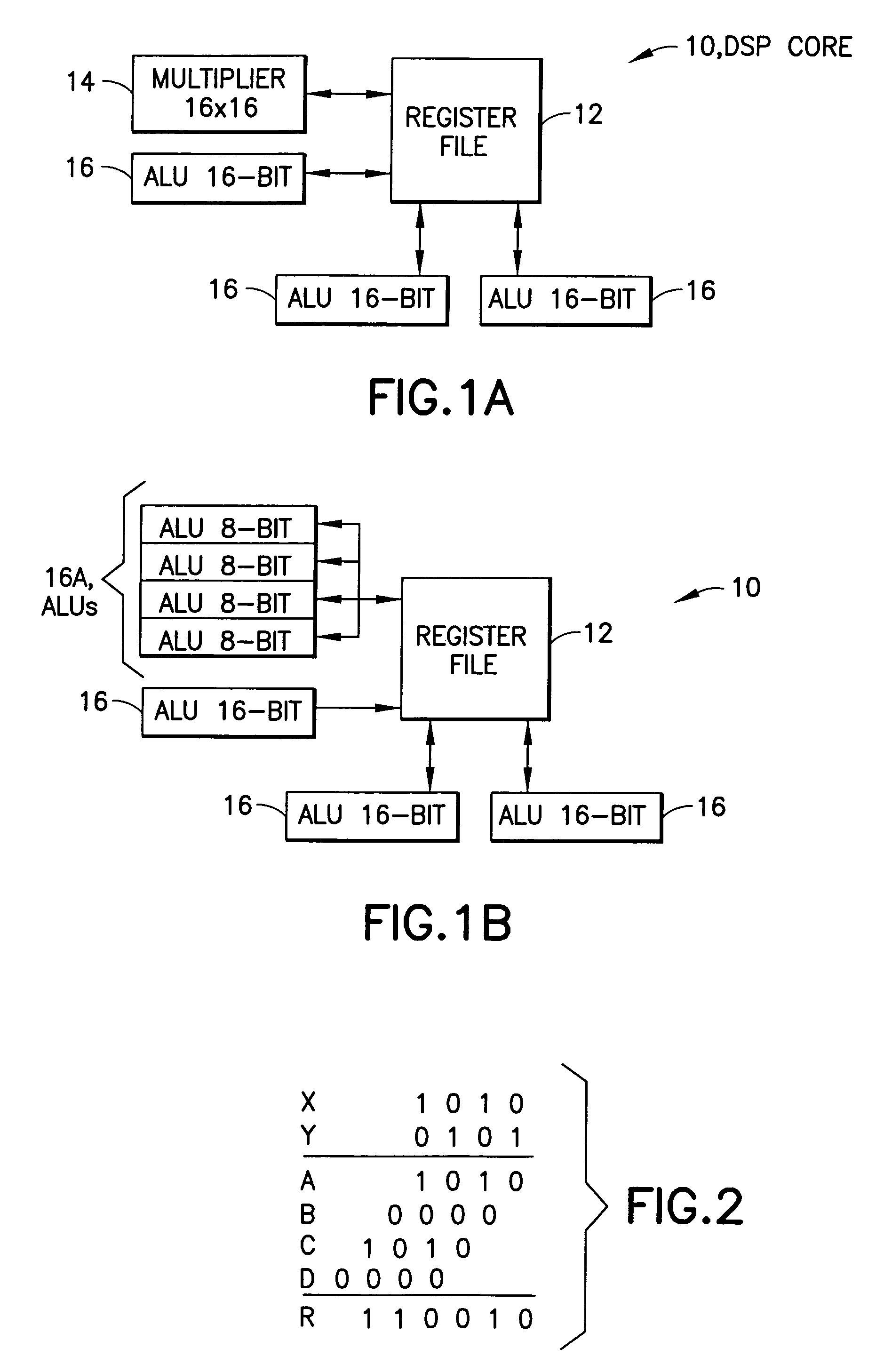
[0038]Reference is first made to FIG. 1A for showing a simplified block diagram of a basic DSP core 10 having a register file 12, a 16×16-bit multiplier 14, and a plurality (e.g., three) of 16-bit ALUs 16. This diagram is not intended to be read in a limiting sense, as more than one multiplier block 14 may be present, and more or less than three ALUs 16 may be used. Other circuitry will also normally be present, including an instruction decode unit and pipeline, an address generator, a barrel shifter, input / output registers and other circuitry. Furthermore, the multiplier 14 and ALUs 16 could have more or less than 16-bits of precision (e.g., they could be 32-bit devices).

[0039]FIG. 1B is a block diagram of the DSP core 10 of FIG. 1 when programmably reconstructed so as to provide a plurality of additional ALUs, for example four 8-bit ALUs 16A, in place of the multiplier 14. In this embodiment the multiplier block 14 is controlled by code to function as additional ALUs, as opposed t...


PUM


Abstract

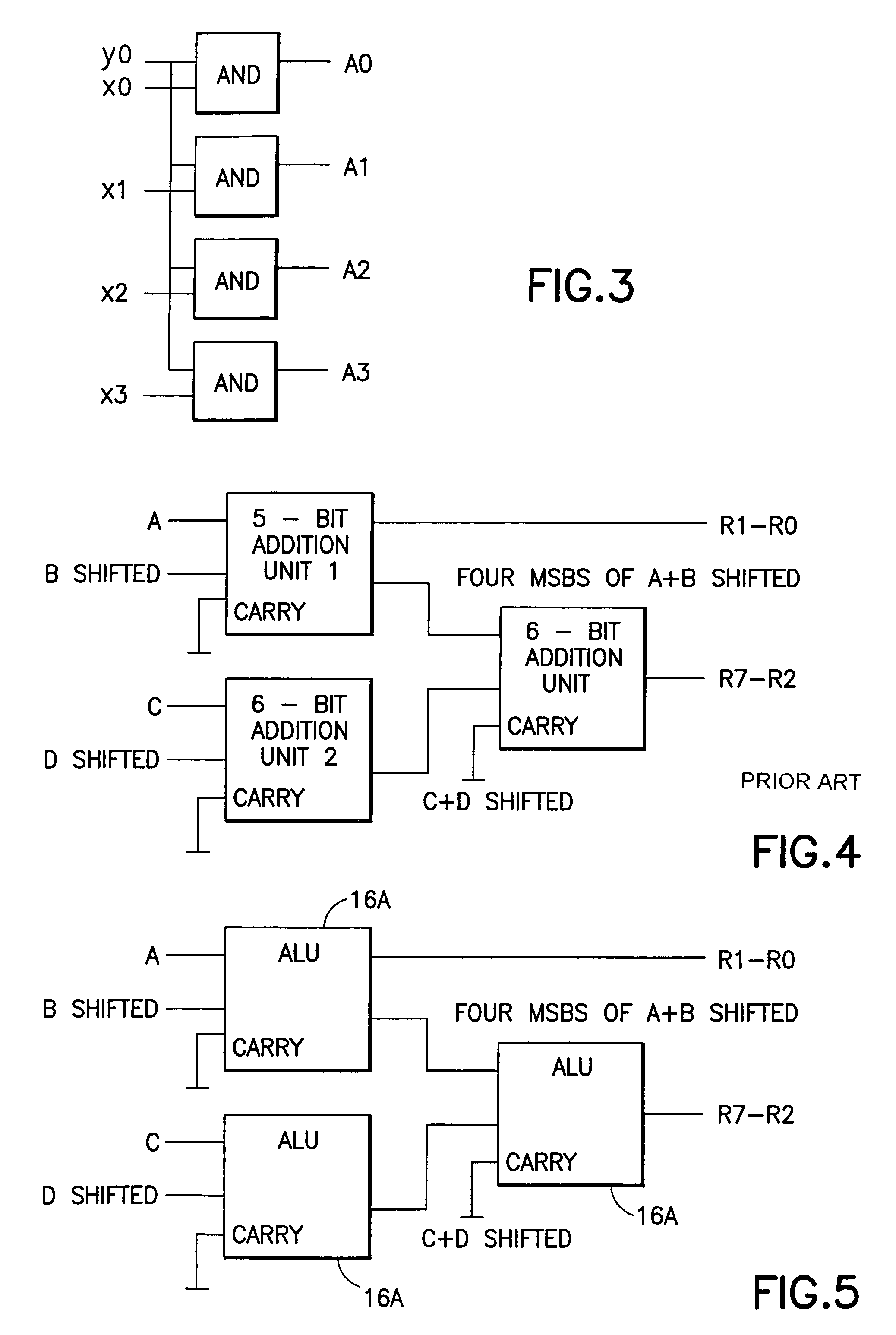
A data processor, such as a DSP, includes a multiplier block having a multiplier front end for generating partial products from input operands, and further includes a plurality of ALUs having inputs that are switchably or programmably coupled, in a first mode of operation, to first data sources representing outputs of the multiplier front end. In the first mode of operation the ALUs add together partial products received from the multiplier front end to arrive at a multiplication result. In a second mode of operation the inputs of the plurality of ALUs are switchably or programmably coupled to second data sources for performing at least one of arithmetic and logical operations on data received from the second data sources.

Description

FIELD OF THE INVENTION[0001]This invention relates generally to data processors and, more particularly, to data processors having processing resources or elements that can be selectively switched between at least two configurations.BACKGROUND OF THE INVENTION[0002]Modern digital data processors, such as Digital Signal Processors (DSPs), are being applied in numerous different types of applications, including broadband communications, medical-imaging equipment, modems, audio equipment, motor control and others. One important application that is of most interest to the teachings of this invention is in the field of wireless telecommunications, such as cellular telephones and personal communications, referred to herein generally as wireless terminals. Other applications of interest include base stations for wireless terminals, as well as internet computing.[0003]One approach to designing a modern wireless terminal is to employ application specific integrated circuit (ASIC) technology a...

Claims


Application Information

Patent Timeline
Patent Type & Authority Patents(United States)
IPC IPC(8): G06F9/302G06F7/57G06F7/52G06F7/48
CPCG06F7/5306G06F7/57G06F9/3001G06F2207/382G06F2207/3828
Inventor PARVIAINEN, JARI A.
Owner HTC CORP
Why Eureka
Eureka Blog
Learn More