Network packet tracking

a network packet and packet tracking technology, applied in the field of communication networks, can solve problems such as failure to provide further information as to the source and location of the problem within the network, failure to test and troubleshoot, and insufficient network performan

Inactive Publication Date: 2005-10-25
CISCO TECH INC
View PDF16 Cites 66 Cited by
  • Summary
  • Abstract
  • Description
  • Claims
  • Application Information

AI Technical Summary

Benefits of technology

[0011]It is an object of some aspects of the present invention to provide improved methods and apparatus for locating faults within communication networks.
[0013]In preferred embodiments of the present invention, a distributed testing system for evaluation and / or testing of a communication network comprises a plurality of capture-capable network agents (CCNAs), which are coupled to the network at different, respective locations and are controlled by a testing center. The CCNAs intercept packets meeting a filtering criterion that is specified by the testing center, and report to the testing center on the arrival of the specified packets. In intercepting the packets, the CCNAs preferably copy the packets “on the fly,” without stopping or delaying the packets. By collecting reports from multiple CCNAs that intercept a given packet passing through the network from one end-point to another, the testing center is able to analyze details of the route and timing of the packet within the network, over multiple links and nodes simultaneously. It thus overcomes a shortcoming of network diagnostic systems known in the art, which are largely limited to determining end-to-end information regarding packet transmission.

Problems solved by technology

A major issue in both newly-deployed and existing communication networks is testing and trouble-shooting, i.e., checking whether the network is operating according to its specifications and, if not, determining the cause of the network's inadequate performance (for example, the identity of a faulty unit or link).
When there is excessive delay or jitter in delivery of the packets, it is an indication that a problem exists.
End-to-end tests by themselves, however, provide no further information as to the source and location of the problem within the network.
When multiple paths are available in the network, however (as is the case in most large IP networks), there is no assurance that all of the packets in the sequence will follow the same path.

Method used


Image

  • Network packet tracking
  • Network packet tracking
  • Network packet tracking

Examples


Embodiment Construction

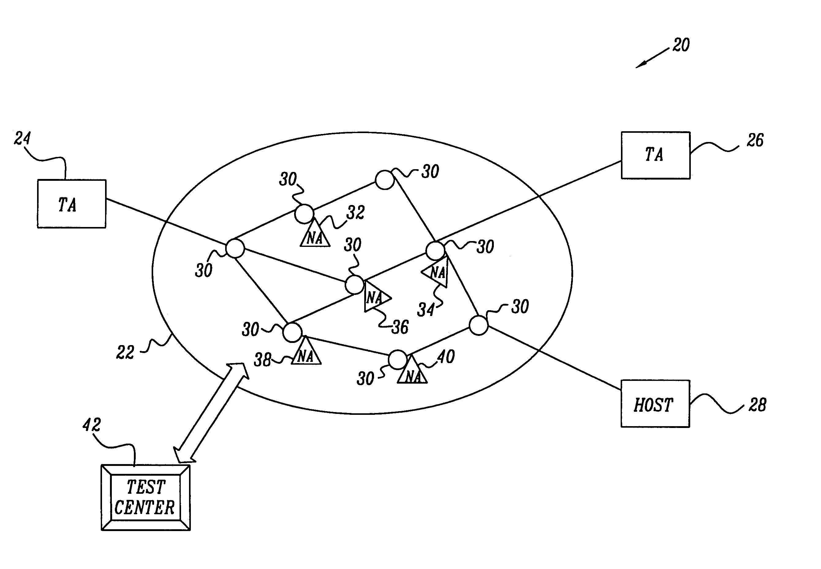
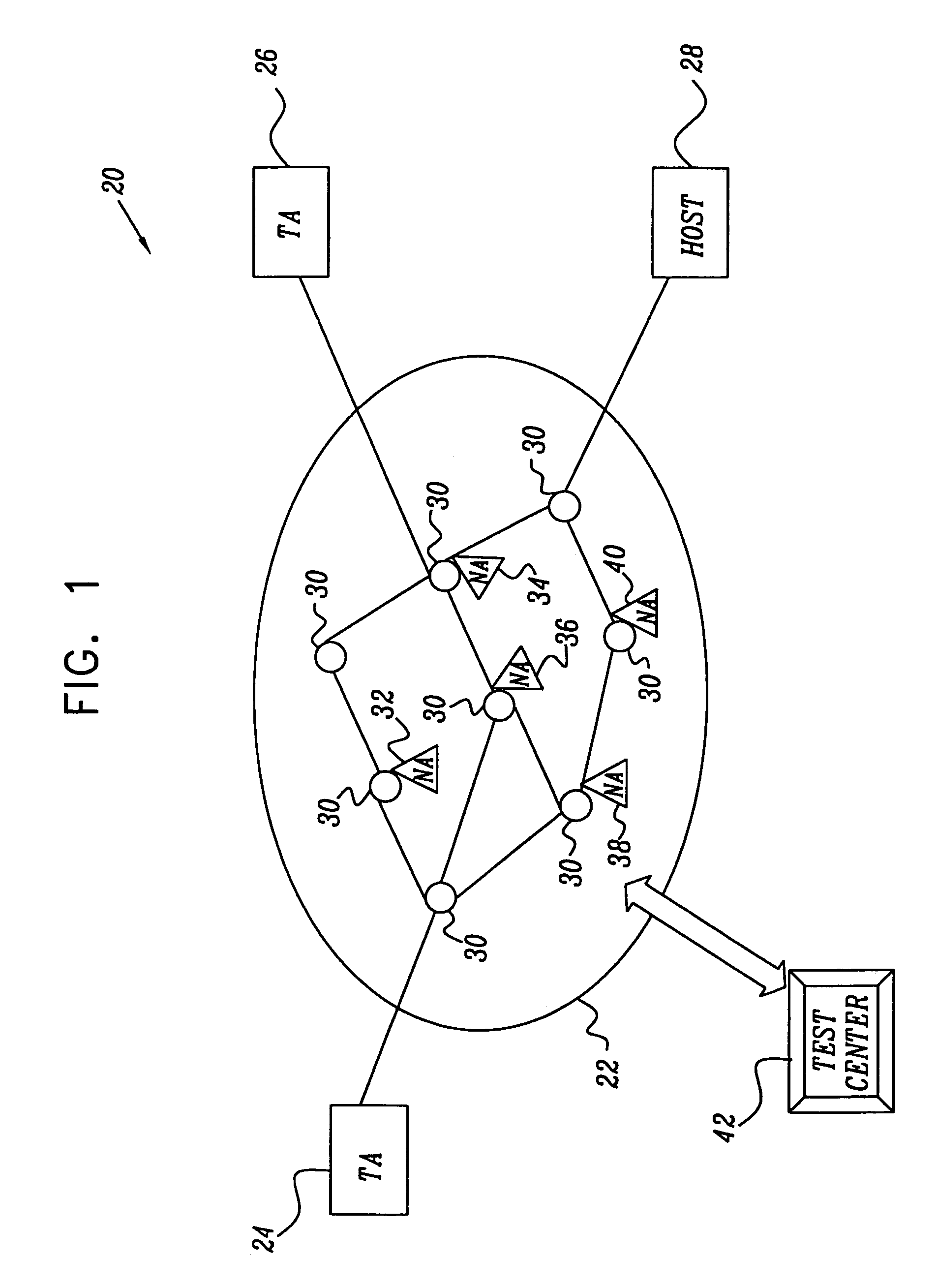
[0037]FIG. 1 is a block diagram that schematically illustrates a distributed testing system 20, used to perform diagnostic testing on a network 22, in accordance with a preferred embodiment of the present invention. Network 22 may comprise substantially any network known in the art that is capable of transmitting data packets, such as a local- or wide-area network (LAN or WAN), a public switched telephone network (PSTN), the Internet or an intranet, an asynchronous transfer mode (ATM) network, an optical or wireless network, or some combination of these different types. The network comprises switching and routing hardware, represented schematically in FIG. 1 as nodes 30.

[0038]Testing system 20 comprises one or more end-point traffic agents 24, 26, which are coupled to ports of network 22. Typically, multiple host computers, such as a host 28, are also connected to and make use of the network. Preferably, the traffic agents serve as both traffic generators, transmitting packets throu...


PUM


Abstract

A method for testing of a communication network having a plurality of end-points, using one or more network agents coupled to the network at respective locations. The method includes specifying at least one packet filtering criterion, and transmitting one or more data packets meeting the at least one criterion through the network from one of the end-point to another. At least one of the data packets meeting the criterion is intercepted using the network agents at one or more of the respective locations in the network traversed by the at least one of the data packets. Information regarding the at least one intercepted packet at the one or more respective locations is recorded and processed to analyze a route of the at least one intercepted packet through the network.

Description

FIELD OF THE INVENTION[0001]The present invention relates generally to communication networks, and specifically to testing and fault discovery in communication networks.BACKGROUND OF THE INVENTION[0002]Communication networks are in wide use in many technological fields including distributed computing, data exchange and telecommunication applications. Communication networks generally include many nodes, such as bridges, LAN switches, routers, cross-connections and telephone switches. The networks further include communication links, such as cables, point-to-point radio connections and optical fibers, which connect the nodes. The networks also include ports, generally within some of the nodes, for attaching external devices such as computers, terminals, handsets, and multiplexers. These external devices are referred to as end-points, or hosts.[0003]A major issue in both newly-deployed and existing communication networks is testing and trouble-shooting, i.e., checking whether the netwo...

Claims


Application Information

Patent Timeline
IPC IPC(8): H04L12/26H04L12/24
CPCH04L12/2697H04L41/046H04L43/028H04L43/50H04L43/0864H04L43/10
Inventor MITRANI, ROEEHORN, LIORKEIDAR, URISIDI, MOSHECIDON, ISRAEL
Owner CISCO TECH INC
Why Eureka
Try Eureka