Apparatus and method for facilitating cooling of an electronics system

a technology for electronics systems and apparatuses, applied in the direction of electrical apparatus casings/cabinets/drawers, domestic cooling apparatus, instruments, etc., can solve the problems of difficult cooling and problematic approach

Active Publication Date: 2009-06-18
IBM CORP
View PDF42 Cites 157 Cited by
  • Summary
  • Abstract
  • Description
  • Claims
  • Application Information

AI Technical Summary

Benefits of technology

[0004]The shortcomings of the prior art are overcome and additional advantages are provided through the provision of an apparatus for facilitating cooling of an air-cooled electronics system, wherein the air-cooled electronics system includes a system housing containing at least one electronics subsystem to be cooled. The apparatus includes a vapor-compression heat exchange system, a front cover and a back cover. The refrigerant-based, vapor-compression heat exchange system includes an evaporator housing and an evaporator disposed therein. The evaporator housing is configured to couple to a first side of the system housing to at least partially extend between an air inlet side and an air outlet side of the system housing. The evaporator housing includes an air inlet opening and an air outlet opening, and the vapor-compression heat exchange system further includes a vapor-compression unit in fluid communication with the evaporator for exhausting heat from the refrigerant circulating therethrough. The front cover is configured to mount to at least one of the system housing or the evaporator housing adjacent to the air inlet side of the system housing and the air outlet opening of the evaporator housing, and the back cover is configured to mount to at least one of the system housing or the evaporator housing adjacent to the air outlet side of the system housing or the air inlet opening of the evaporator housing. Together, the system housing, back cover, evaporator housing and front cover facilitate establishing a closed loop airflow path extending through the air inlet and air outlet sides of the system housing and through the air inlet and air outlet openings of the evaporator housing. When operational, the vapor-compression heat exchange system at least partially cools air circulating through the closed loop airflow path, thereby facilitating cooling of the at least one electronics subsystem of the electronics system.

Problems solved by technology

This trend poses a cooling challenge at both the module and system level.
However, this approach is becoming problematic at the system level.

Method used


Image

  • Apparatus and method for facilitating cooling of an electronics system
  • Apparatus and method for facilitating cooling of an electronics system
  • Apparatus and method for facilitating cooling of an electronics system

Examples


Embodiment Construction

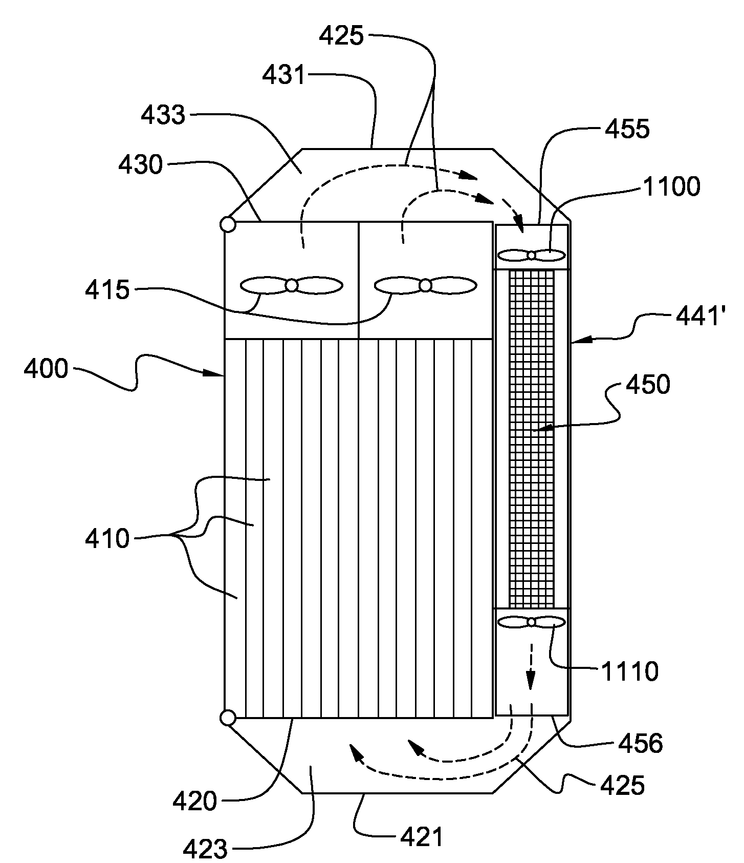
[0022]As used herein, the term “electronics system”, includes any housing, frame, compartment, blade server system, etc., having one or more heat generating components of a computer system, and may be, for example, a stand alone computer processor having high, mid or low end processing capability. In one embodiment, an electronics system may comprise multiple electronics subsystems, each having one or more heat generating components disposed therein requiring cooling. “Electronics subsystem” refers to any sub-housing, blade, book, drawer, node, compartment, etc., having one or more heat generating electronics components disposed therein. Electronics subsystems of an electronics system may be movable or fixed relative to the electronics system, with the blades of a blade center system being one example of subsystems of an electronics system to be cooled.

[0023]“Vapor-compression heat exchange system” means any heat exchange mechanism characterized as described herein through which ref...


PUM

PropertyMeasurementUnit
poweraaaaaaaaaa
temperatureaaaaaaaaaa
rotational speedaaaaaaaaaa

Abstract

Apparatus and method are provided for facilitating air-cooling of an electronics system employing a vapor-compression heat exchange system, and front and back covers. An evaporator housing of the heat exchange system is mounted to a system housing of the electronics system and extends at least partially between air inlet and outlet sides of the system housing. The evaporator housing includes air inlet and outlet openings, and an evaporator. The front cover is mounted to the system or evaporator housing adjacent to the air inlet side or air outlet opening, and the back cover is mounted to the system or evaporator housing adjacent to the air outlet side or air inlet opening. Together, the system housing, back cover, evaporator housing and front cover define a closed loop airflow path passing through the system housing and evaporator housing, with the vapor-compression heat exchange system cooling air circulating therethrough.

Description

TECHNICAL FIELD[0001]The present invention relates in general to apparatuses and methods for facilitating cooling of an electronics system, such as a multi-blade center system, and more particularly, to apparatuses and methods for facilitating air-cooling of an electronics system by employing a vapor-compression heat exchange system and a closed loop airflow path through the electronics system to be cooled.BACKGROUND OF THE INVENTION[0002]The power dissipation of integrated circuit chips, and the modules containing the chips, continues to increase in order to achieve increases in processor performance. This trend poses a cooling challenge at both the module and system level. Increased air flow rates are needed to effectively cool high power modules and to limit the temperature of the air that is exhausted into the computer center.[0003]In many server applications, processors along with their associated electronics (e.g., memory, disk drives, power supplies, etc.) are packaged in rem...

Claims


Application Information

Patent Timeline
Patent Type & Authority Applications(United States)
IPC IPC(8): H05K7/20F25B1/00B23P11/00
CPCF25D17/06F25D2317/0655Y10T29/49826H05K7/20754F25D2317/0661
Inventor IYENGAR, MADHUSUDAN K.KAMATH, VINODMATTESON, JASON A.SCHMIDT, ROGER R.STEINKE, MARK E.
Owner IBM CORP
Why Eureka
Try Eureka