Low momentum loss fluid manifold system

a fluid manifold and low momentum loss technology, applied in the field of liquid cooling thermal management systems, can solve the problems of liquid cooling being liquid cooling a single processor may require a cost premium, and the cost of liquid cooling can be more expensive than air cooling, so as to achieve the effect of low momentum loss

Inactive Publication Date: 2005-10-25
PARKER INTANGIBLES LLC
View PDF15 Cites 34 Cited by
  • Summary
  • Abstract
  • Description
  • Claims
  • Application Information

AI Technical Summary

Benefits of technology

[0019]In order to solve the problems of the prior art, and to provide a liquid cooling solution that allows multiple components to be cooled in parallel, a low momentum loss fluid manifold system has been developed.
[0020]The present invention is a two-phase liquid cooling system that cools a plurality of electronic components connected in parallel. A pump delivers a cooling fluid, as a liquid, to a supply manifold wherein it splits into distinct branch lines. Preferably, the branch lines feed coolant to individual spray modules. The liquid coolant removes heat from the components to be cooled through evaporation. The resulting liquid and vapor mixture exits the spray modules via return branches. Each individual return branch feeds into a return manifold at an acute angle. The acute angular transitions between the return branches and the return manifold provides low momentum losses and a more efficient system. In addition, the conservation of return fluid momentum in each of the return branches helps draw fluid from other return branches in the system.

Problems solved by technology

As air cooling heat sinks continue to be pushed to new performance levels, so has their cost, complexity, and weight.
Although both single-phase and two-phase liquid cooling solutions provide many advantages over air cooling solutions, they also have drawbacks.
One such drawback is that liquid cooling can be more expensive than air cooling.
Although the performance of liquid cooling may justify the increased cost over air cooling, liquid cooling a single processor may require a cost premium.
A significant problem with series connections is that the cooling fluid is at a different thermal state at each electronic component along the chain.
Thermal cycling reduces component reliability.
Parallel connections remedy the disadvantages of series connections, but it too creates challenges.
A first challenge with parallel connections using two-phase flow is that the flow of fluid can be complicated.
The mode of flow can be difficult to predict and tests have shown the mode of flow to have a significant impact on the performance of a cooling system.
Another problem with parallel connections is that the numerous transitions can cause system back-pressures.
Back-pressures, or restrictions downstream of a spray module, can cause an increased pressure level within a spray module.
Increased spray module pressures decrease vaporization and overall heat transfer rates.
In addition, back-pressures create system inefficiencies as the pump must perform additional work.
Yet another problem with parallel connections is that in many computer cooling applications, the locations of particular processors may not be fixed.

Method used


Image

  • Low momentum loss fluid manifold system
  • Low momentum loss fluid manifold system
  • Low momentum loss fluid manifold system

Examples


Embodiment Construction

[0028]Many of the fastening, connection, manufacturing and other means and components utilized in this invention are widely known and used in the field of the invention are described, and their exact nature or type is not necessary for a person of ordinary skill in the art or science to understand the invention; therefore they will not be discussed in detail.

[0029]Applicant hereby incorporates by reference U.S. Pat. No. 5,220,804 for a high heat flux evaporative cooling system. Although spray cooling is herein described as the preferred method of two-phase cooling, the present invention is not limited to such a system. Spray cooling is only discussed in detail to provide a known preferred embodiment.

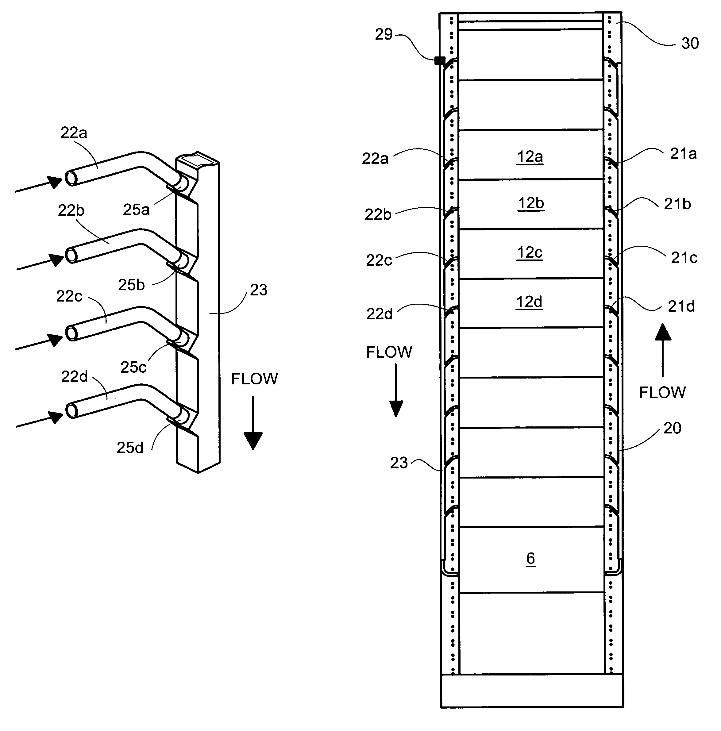
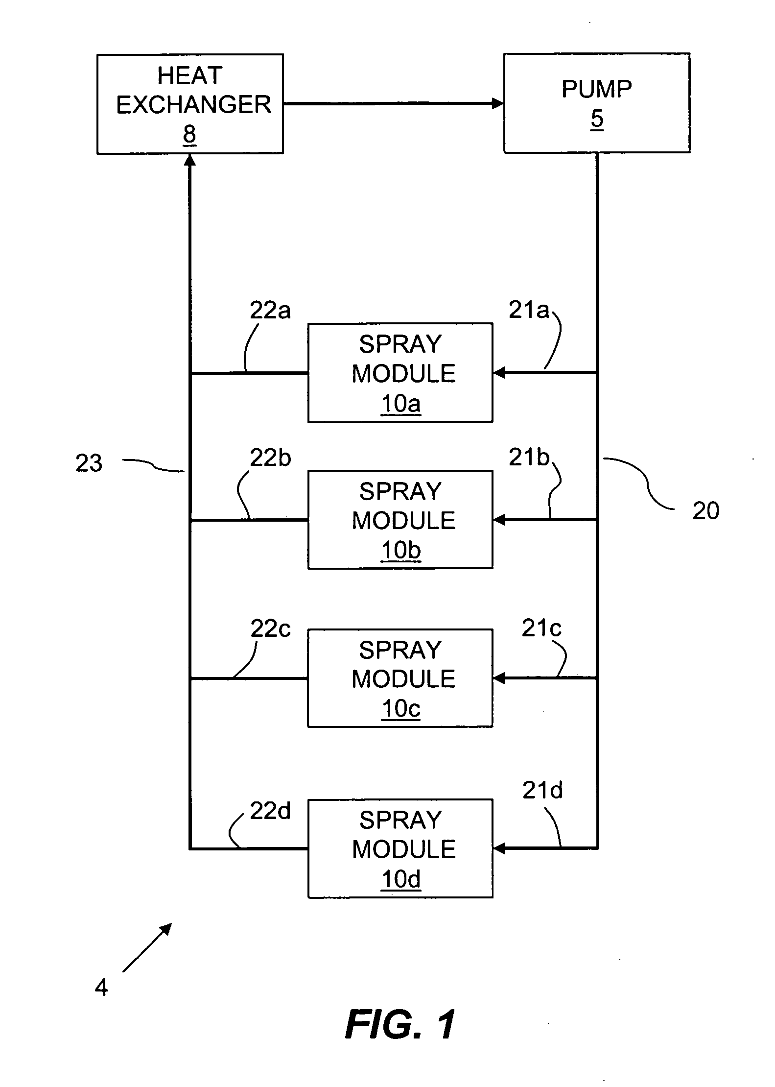
[0030]Now referring to FIG. 1, a two-phase thermal management system 4 is shown. A cooling fluid (not shown) is pressurized by a pump 5. An exemplary cooling pump 5 is described by U.S. Pat. No. 6,447,270. The cooling fluid may be any one of a wide range of commonly known dielectric or n...


PUM


Abstract

The present invention is a two-phase liquid cooling system that cools a plurality of electronic components connected in parallel. A pump delivers a cooling fluid, as a liquid, to a supply manifold wherein it splits into distinct branch lines. Preferably, the branch lines feed coolant to individual spray modules. The liquid coolant removes heat from the components to be cooled. The resulting liquid and vapor mixture exit the spray modules via a plurality of return branches. Each individual return branch feeds into a return manifold at an acute angle. The angular transitions between the return branches and the return manifold provides low manifold losses and a more efficient system.

Description

CROSS REFERENCE TO RELATED APPLICATIONS[0001]NoneSTATEMENT REGARDING FEDERALLY SPONSORED RESEARCH OR DEVELOPMENT[0002]Not related to this application.BACKGROUND[0003]1. Field of the Invention[0004]The present invention relates generally to liquid cooling thermal management systems and more specifically it relates to a two-phase liquid cooling management system that provides economies of scale with consistent high performance through the use of a low momentum loss fluid manifold system.[0005]2. Description of the Related Art[0006]Liquid cooling is well known in the art of cooling electronics. As air cooling heat sinks continue to be pushed to new performance levels, so has their cost, complexity, and weight. Liquid cooling systems provide advantages over air cooling systems in terms of heat removal rates, component reliability and package size.[0007]Liquid cooling systems are comprised of many different species. Although each specie may have unique advantages and disadvantages, they ...

Claims


Application Information

Patent Timeline
Patent Type & Authority Patents(United States)
IPC IPC(8): F25D23/12H05K7/20
CPCH05K7/20345
Inventor CADER, TAHIRRESSA, ROBERT J.
Owner PARKER INTANGIBLES LLC
Why Eureka
Try Eureka