
Viscous fluid metering device with quick change nozzle

Inactive Publication Date: 2005-10-25
ERDMAN AUTOMATION CORP
View PDF9 Cites 7 Cited by
  • Summary
  • Abstract
  • Description
  • Claims
  • Application Information

AI Technical Summary

Benefits of technology

[0015]It would be desirable to have a durable metering device that has minimal leakage and a quick disconnect nozzle assembly that can be rapidly connected and disconnected and fitted onto the nozzle holder manually without the use of a tools. Preferably the nozzle assembly should provide a leak-proof connection with the fluid source that can be easily positioned in a preferred orientation. The assembly should be easily inspected, have few moving parts and easily replaceable sealing members. In addition, the nozzle assembly should allow for repeatable positioning of the nozzle.
[0017]Another trend seen in the adhesives industry is toward the use of two part catalyzed sealants. Two part catalyzed sealants also include high levels of abrasive and corrosive components. These qualities accelerate wear on dispensing system components. Thus, both durability and ease of maintenance are important qualities for equipment used to dispense these types of sealants.
[0018]While it is desirable, in hot applied sealant systems, to maintain the fluid passage ways at a high temperature in order keep the sealants fluid, it is undesirable to expose mechanical components such as servo motors, gear boxes and actuators to high temperatures. Exposing these components to elevated temperatures tends to accelerate wear and increase the likelihood of early component failure.
[0019]The present invention solves many of the above problems by providing a robust gear metering device and an easily changeable nozzle and holder assembly.
[0021]The invention includes a gear metering device suited to delivering viscous fluids such as sealants and desiccants used in the window manufacturing industry. The metering device includes a gear metering device chamber enclosed within metering device body assembly and transfers fluid under pressure to the outlet of the metering device. A significant feature of the present invention is that the surface finish of the gear teeth and clearances between gear teeth and the walls of the metering chamber are held to tight tolerances so that pressure generated by the motion of the gears is not dissipated through leak paths in the metering chamber. Another significant feature of the present invention is the use of materials of construction and seals uniquely adapted to resist deterioration under contact with the abrasive and caustic chemicals in sealants.

Problems solved by technology

The ease of replacement of a nozzle can significantly affect machine utilization.
A further problem encountered with hot applied sealants is when they are subjected to high pressures, solids in the hot applied sealant mix will tend to come out of suspension.
For example, if a hot applied sealant material can only be subjected to a maximum pressure of 2,500 psi and there is a pressure loss passing through the passageways of the system of 1,000 psi, this can create a major problem in maintaining high enough levels of pressure in the lowest pressure areas of the system while keeping high pressure areas below the critical pressure.

Method used


Image

  • Viscous fluid metering device with quick change nozzle
  • Viscous fluid metering device with quick change nozzle
  • Viscous fluid metering device with quick change nozzle

Examples


Embodiment Construction

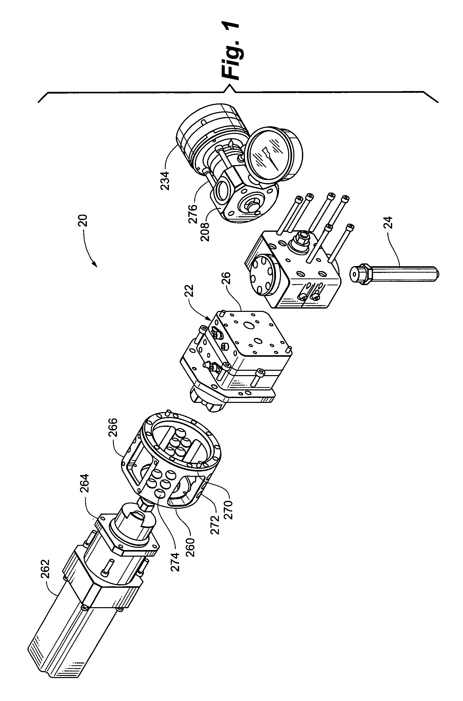
[0052]Referring to FIG. 1, viscous liquid dispenser 20 generally includes a metering device 22 and a nozzle assembly 24. Metering device 22 is in fluid communication with nozzle assembly 24 so that viscous liquid material that leaves metering device 22 flows to and, ultimately through nozzle assembly 24. The metering device 22 generally includes metering device body 26 and gear assembly 28. Gear assembly 28 is enclosed within and surrounded by metering device body 26.

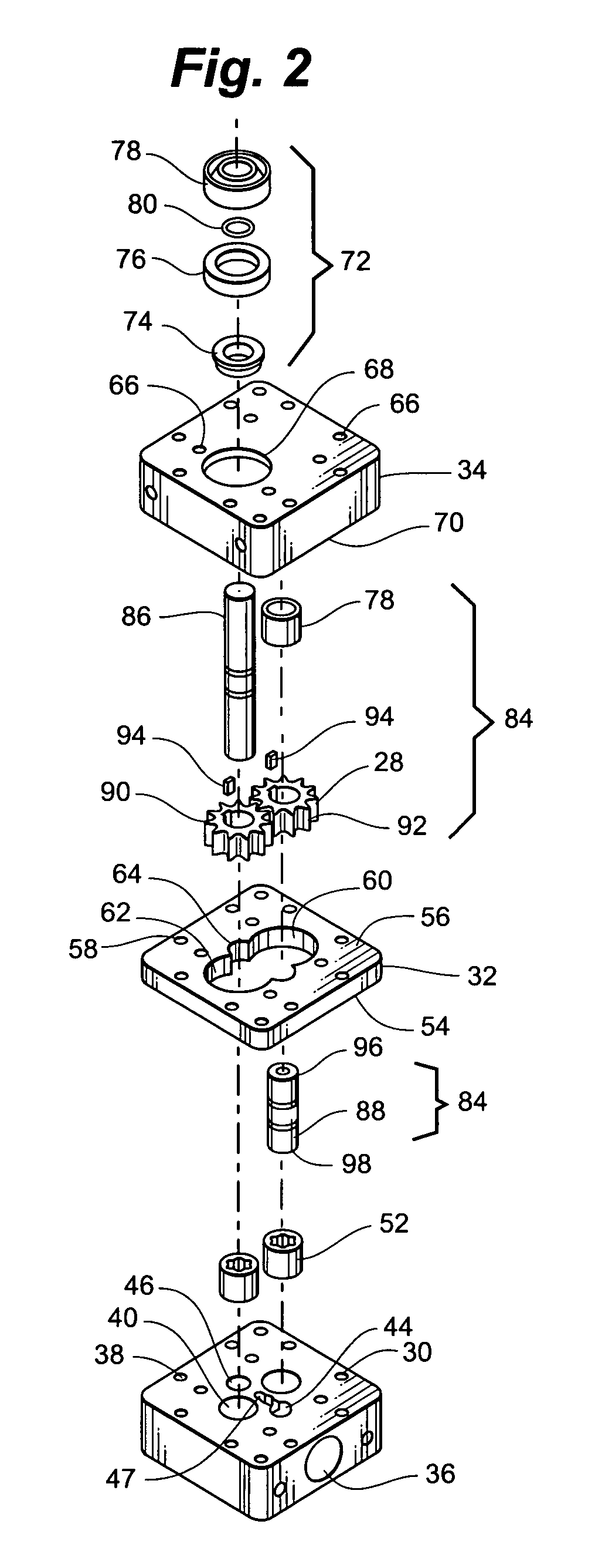
[0053]Referring to FIGS. 2, 20 and 21, metering device body 26 is generally divided into three major subcomponents, port plate 30, center plate 32 and drive plate 34. Each of port plate 30, center plate 32 and drive plate 34 have a plurality of passageways, apertures and cavities machined or otherwise formed in them.

[0054]Port plate 30 defines inlet 36, a plurality of boltholes 38 and bearing cavities 40. Inlet 36 leads to inlet passage 42 which terminates at interior inlet 44. Thus, inlet passage 42 provides for fluid ...


PUM


Abstract

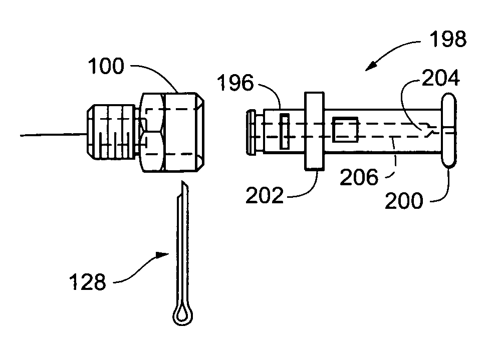
A fouling resistant fluid dispensing assembly including a metering device and a nozzle assembly. The nozzle assembly generally includes a nozzle holder including a body defining a cylindrical bore. The nozzle has a cylindrical portion proportioned to be inserted into the cylindrical bore in a close fitting relationship. The nozzle holder is pierced by a passage oriented substantially perpendicular to the bore axis and passing through the cylindrical bore on a non-diametrical chord and the nozzle has a complementary passage that can be aligned with the nozzle holder passage. Once the holder passage and the nozzle passage are aligned, a retaining member proportioned to pass through the nozzle holder passage and the nozzle passage retains the nozzle in the cylindrical bore. The fluid dispensing assembly further includes a floating head and a mass distribution to maintain a viscous fluid at a desired temperature.

Description

CLAIM TO PRIORITY[0001]This application claims priority to U.S. Provisional Application Ser. Nos. 60 / 452,606 entitled “Quick Change Nozzle” filed Mar. 6, 2003 and 60 / 454,275 entitled “Gear Pump Case” filed Mar. 13, 2003, the entire contents of which are incorporated herein by this reference.RELATED APPLICATIONS[0002]This application is related to U.S. Provisional Application Ser. No. 60 / 452,209 filed Mar. 5, 2003 entitled “System and Process for Glazing Glass to Windows and Door Frames” and to Utility Application filed on Mar. 5, 2004, with the same title, the entire contents of which are incorporated herein by this reference.FIELD OF THE INVENTION[0003]This invention relates to dispensing viscous fluids prone to hardening, such as sealants, and more particularly relates to a metering device and nozzle for dispensing viscous fluids.BACKGROUND OF THE INVENTION[0004]One of the biggest challenges in delivering viscous fluid is providing a uniform, metered flow of viscous material in ap...

Claims


Application Information

Patent Timeline
IPC IPC(8): G01F11/00G01F11/44
CPCG01F11/44
Inventor ERDMAN, RODNEY V.BERNS, ERIC J.
Owner ERDMAN AUTOMATION CORP
Learn More