
Corrosion-resistant body for utility vehicle

a technology for utility vehicles and body parts, applied in the field of utility vehicles, can solve the problems of reducing the strength of welded utility bodies, needing to square compartments and doors, and affecting the so as to achieve the effect of resisting vibration, maximizing strength, and improving reliability and strength of inventive utility bodies

Active Publication Date: 2005-10-18
STAHL SCOTT FETZER
View PDF68 Cites 19 Cited by
  • Summary
  • Abstract
  • Description
  • Claims
  • Application Information

AI Technical Summary

Benefits of technology

"The present invention is a corrosion-resistant utility body for mounting onto a truck chassis. It includes a truck chassis, a cab, and the utility body. The utility body consists of a pair of body side storage compartment units that are mounted along the rear side portions of the chassis. Each unit is comprised of metal panels and sections that form compartments with separate side openings. The storage compartments have adjustable shelves for storing equipment, tools, and supplies. The utility body also includes one-piece face plates with door openings aligned with the side openings. The one-piece face plate has pre-cut holes and a shank that extends through the pre-cut holes. The panels and sections are connected together using swage-type engineered fasteners. The utility body is weld-free and has improved corrosion resistance."

Problems solved by technology

Problems can arise in utility vehicles as a result of the manner or materials used in their construction.
Another potential problem with welding is that the location of the welds, though specified by the utility body manufacturer to maximize strength, may not always be made in the specified locations.
This could lead to reduced strength of welded utility bodies.
Another issue in conventional construction of utility bodies is the need to square compartments and doors.

Method used


Image

  • Corrosion-resistant body for utility vehicle
  • Corrosion-resistant body for utility vehicle
  • Corrosion-resistant body for utility vehicle

Examples


Embodiment Construction

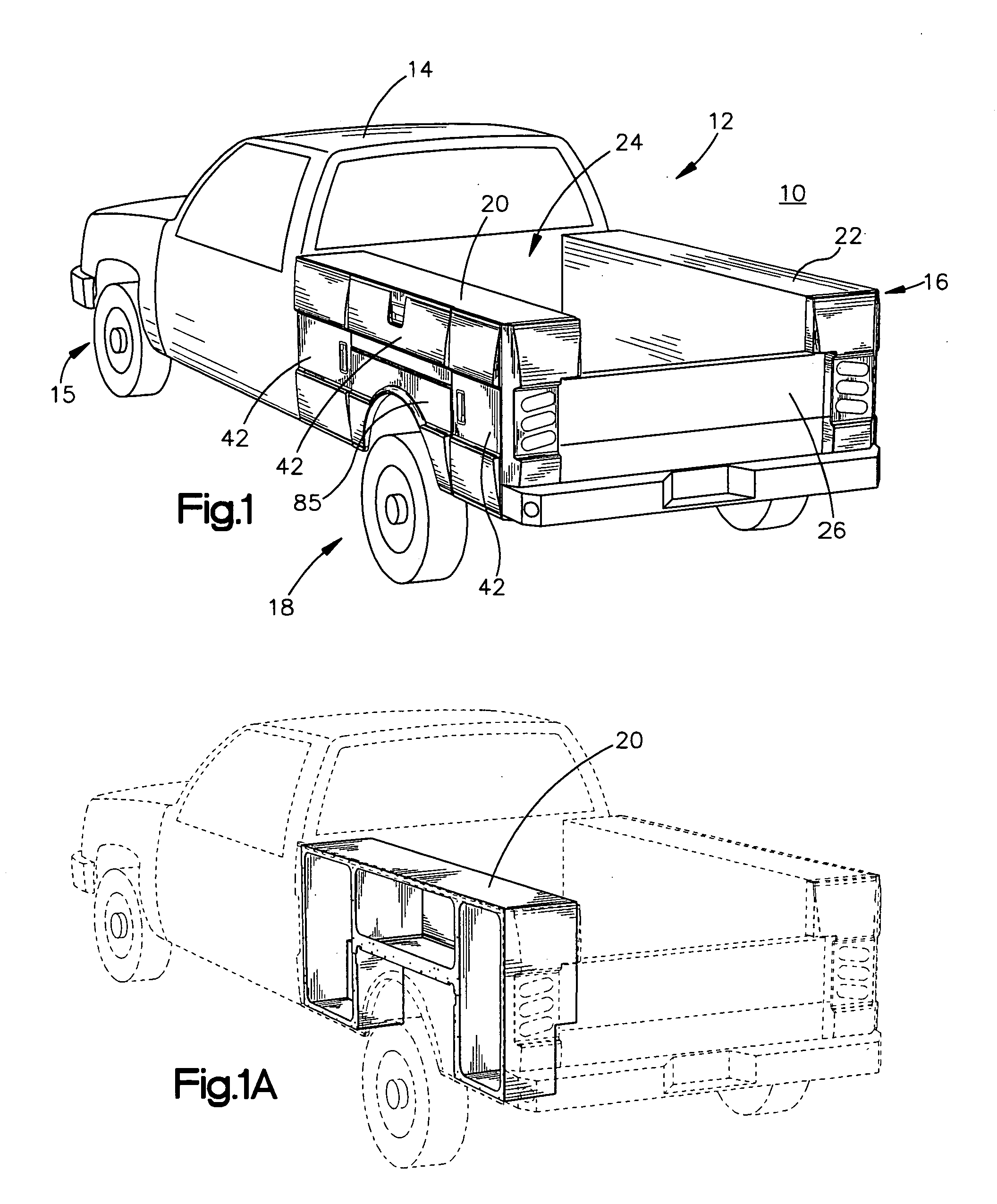
[0020]A utility vehicle 10 constructed according to the present invention comprises a truck chassis 12 without a bed, a cab 14 disposed at a front portion 15 of the chassis, and the inventive corrosion-resistant utility body 16 disposed at a rear portion 18 of the chassis. The corrosion-resistant utility body comprises a pair of body side storage compartment units 20, 22 adapted to be mounted along rear side portions of the truck chassis. Only one storage compartment unit 20 will be described in detail herein, the other storage compartment unit 22 being a mirror image thereof but otherwise preferably having the same features. The front of the storage compartment units are mounted to a bulkhead 24 near the cab. A tailgate 26 is mounted to the rear of the storage compartment units.

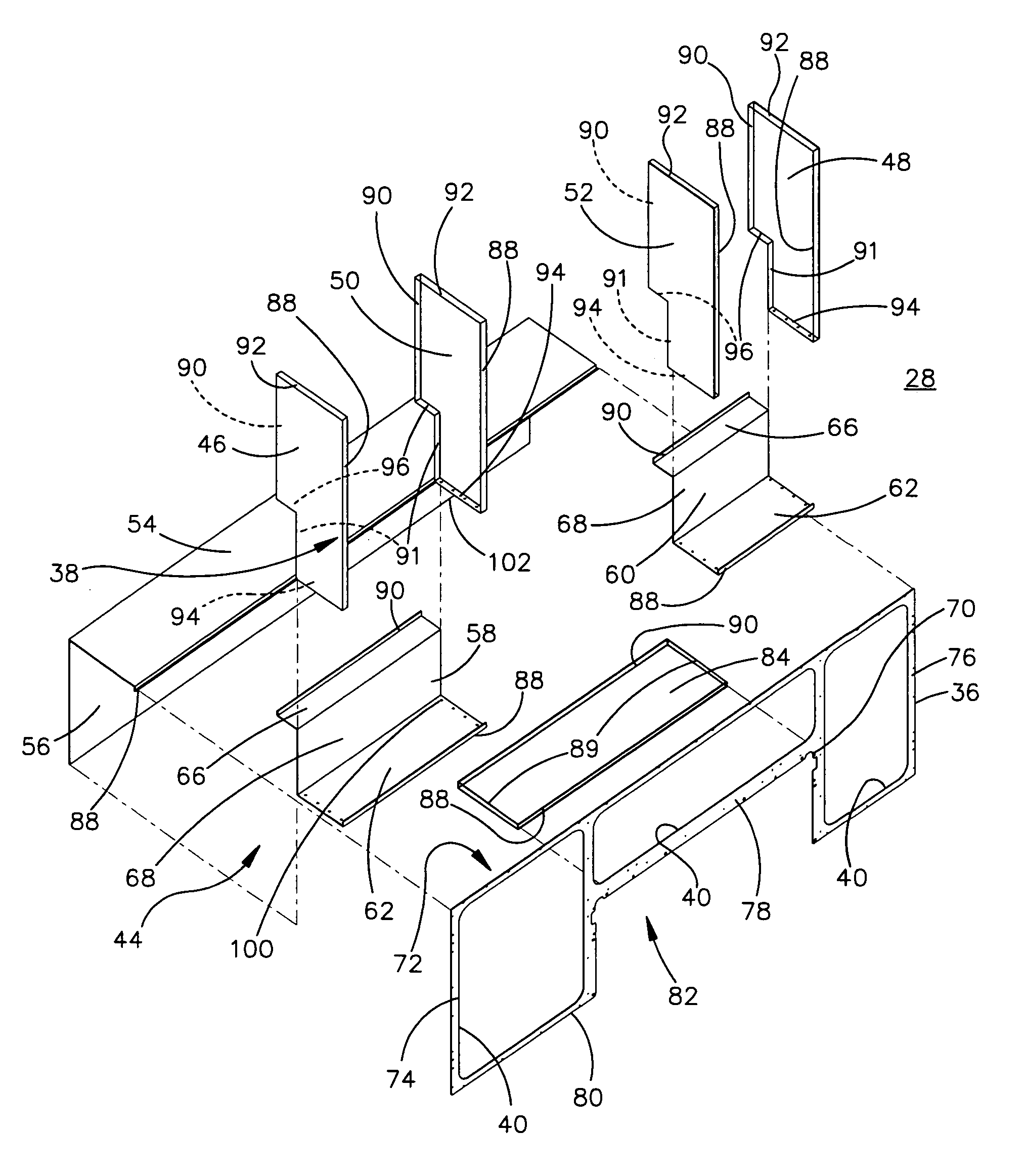
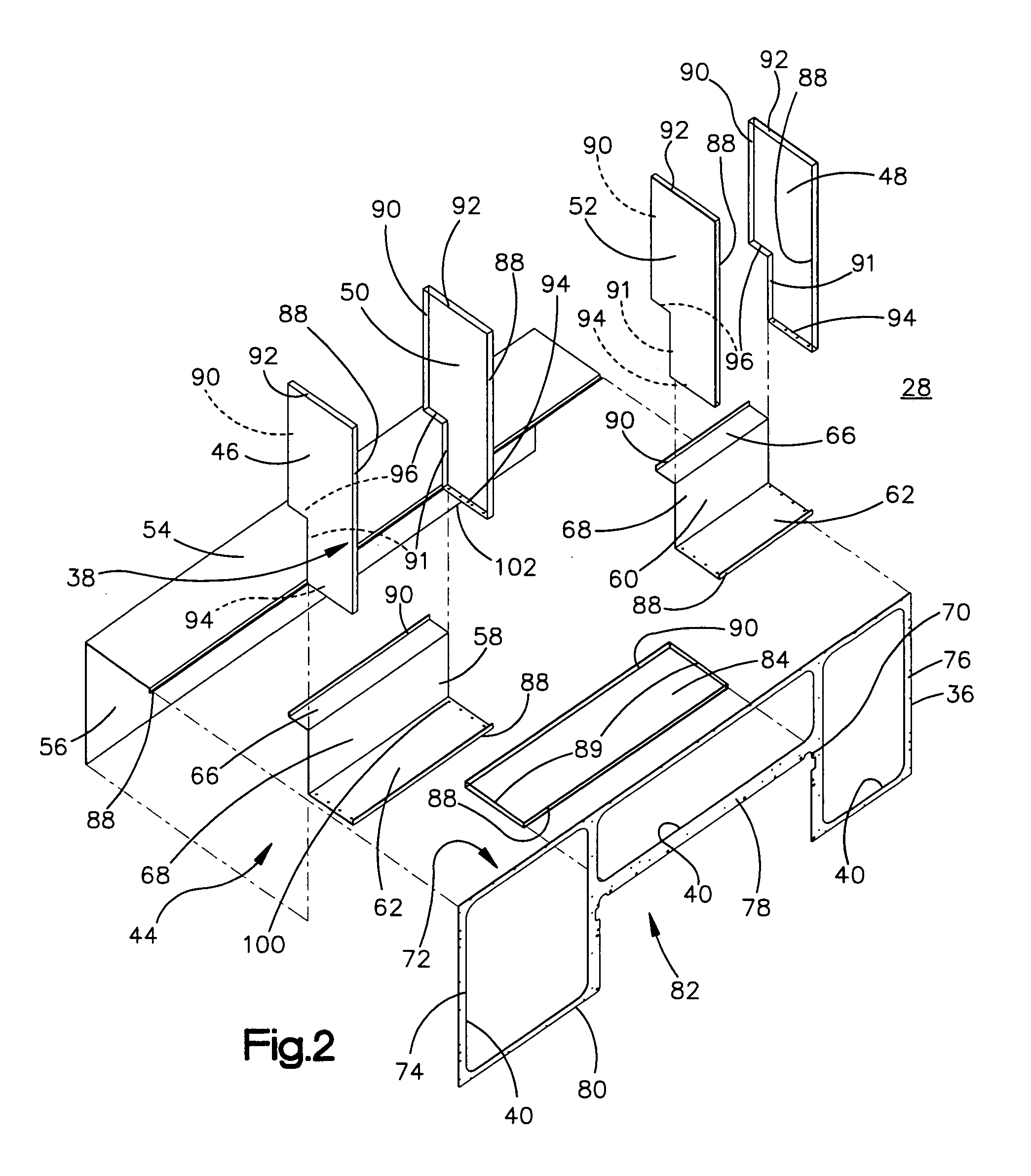
[0021]Each storage compartment unit 20, 22 is comprised of a storage compartment assembly. The storage compartment assembly 28 of the unit 20 (FIGS. 2 and 3) comprises metal walls 30 (a few of which are labe...


PUM


Abstract

A corrosion-resistant utility body comprises a pair of body side storage compartment units adapted to be mounted along rear side portions of a truck chassis. Each storage compartment unit is comprised of a storage compartment assembly that comprises metal walls forming compartments that lead to separate side openings at the outside of the storage compartment assembly. The compartments can include a plurality of vertically spaced adjustable shelves for storing equipment, tools, supplies and the like. An outer one-piece face plate is fastened to outer surfaces of the storage compartment assembly. The one-piece face plate is comprised of metal and includes door openings aligned with each of the side openings of the storage compartment assembly. Door assemblies are connected to the one-piece face plate in alignment with the door openings. A utility vehicle includes a truck chassis, a cab mounted to a front portion of the chassis, and the present utility body mounted to a rear portion of the chassis. The utility body can be constructed using swage-type fasteners and so as to be weld-free. Also featured is a method of constructing the utility body.

Description

FIELD OF THE INVENTION[0001]The present invention relates to utility vehicles and, in particular, to utility bodies that are mounted to a truck chassis of a utility vehicle.BACKGROUND OF THE INVENTION[0002]Utility vehicles include utility bodies mounted to the rear of the chassis of vehicles. The utility bodies have a plurality of storage compartments covered by exterior doors. Utility vehicles are used by companies that have a need for storage, such as telephone companies, electric companies, general contractors, repair companies and the like.[0003]Utility bodies are mounted onto an OEM truck chassis with a cab and no bed. The utility body is mounted onto the rear portion of the chassis in place of the bed. The utility body is provided with a style and color that complement the cab. Utility bodies for such vehicles can have various designs with different numbers, sizes and locations of compartments. Utility bodies typically comprise a pair of body side storage compartment units mou...

Claims


Application Information

Patent Timeline
Patent Type & Authority Patents(United States)
IPC IPC(8): B60N3/00B60N3/12B62D33/02B62D33/03B62D33/023B62D65/02
CPCB62D33/02B62D33/023B62D65/02
Inventor BOYER, THOMAS J.
Owner STAHL SCOTT FETZER
Learn More