
Resonant energy MEMS array and system including dynamically modifiable power processor

a power processor and dynamically modifiable technology, applied in piezoelectric/electrostrictive/magnetostrictive devices, piezoelectric/electrostrictive device details, semiconductor devices, etc., can solve the problems of battery not being a viable solution for embedded sensors, sensors typically needing their own self-powered power supply, etc., to achieve low frequency operation and reduce power loss

Inactive Publication Date: 2005-10-11
UNIV OF FLORIDA RES FOUNDATION INC
View PDF17 Cites 58 Cited by
  • Summary
  • Abstract
  • Description
  • Claims
  • Application Information

AI Technical Summary

Benefits of technology

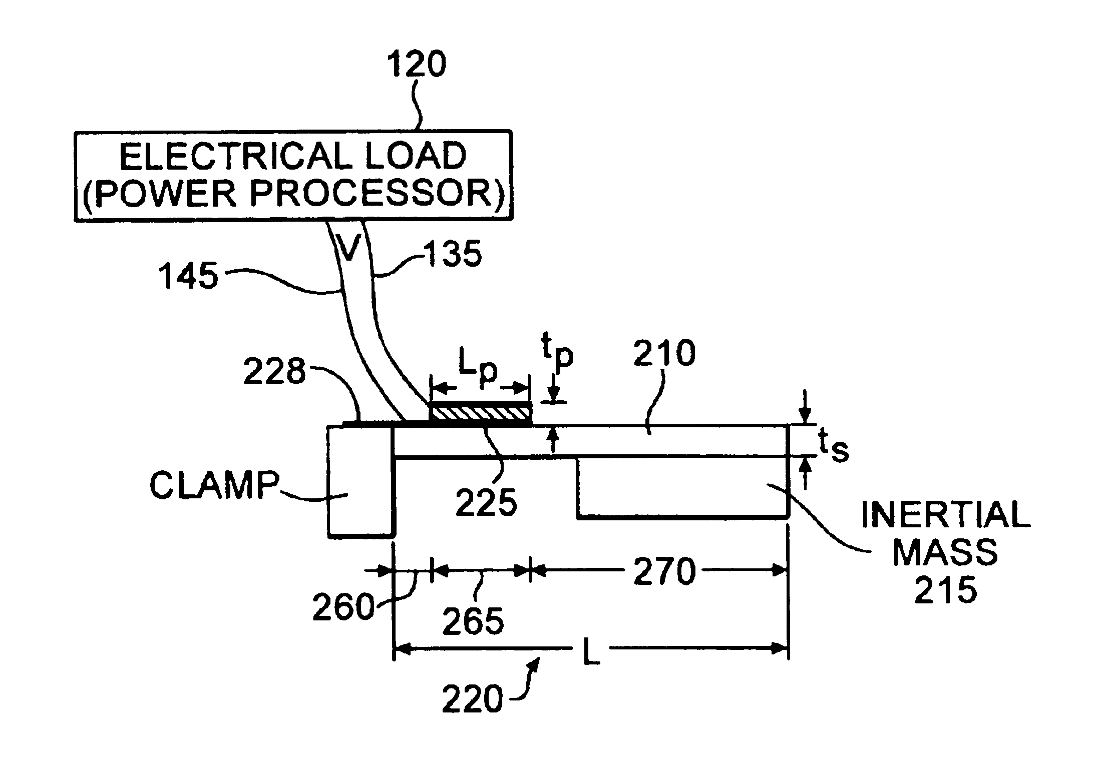
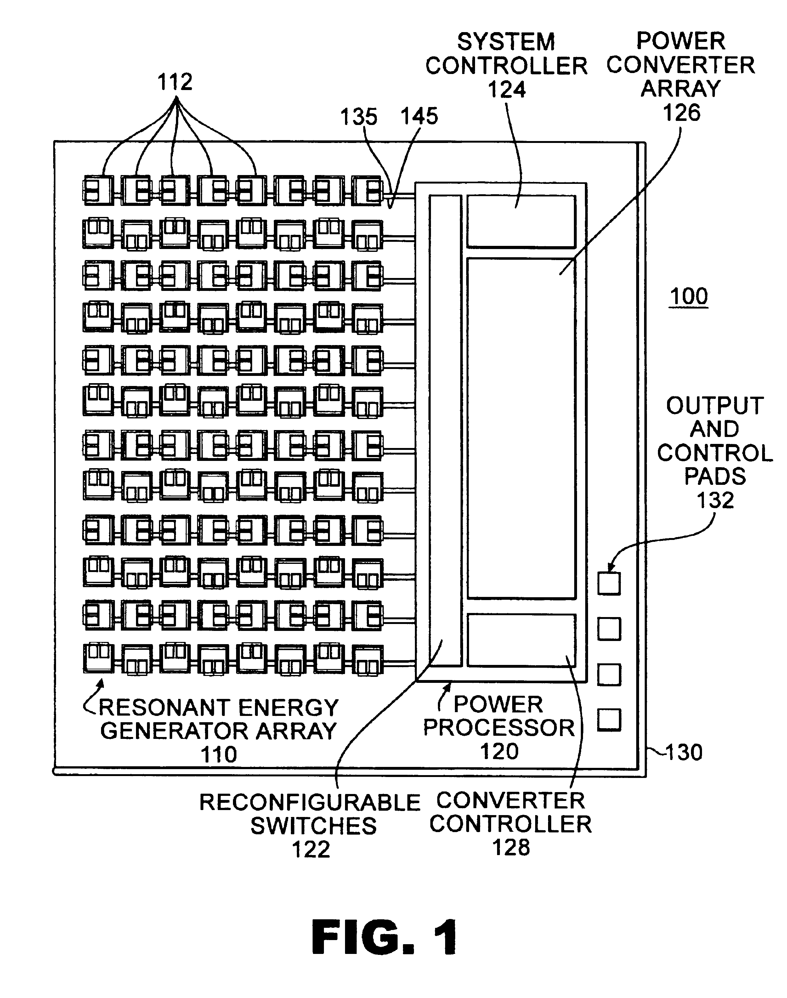
[0014]The power processor preferably includes structure for providing a dynamically adjustable switching function. In one embodiment, the power processor includes a rectifier for providing a rectified output voltage from the voltage output by the micro generators and a controller which includes a peak detector, where dynamic switching of the power processor is based on the peak detector determining instants when the rectified voltage is at a peak value. In another embodiment, the power processor includes a controller which dynamically adjusts an input impedance of the power processor, the input impedance dynamically matching, such as being the complex conjugate, of the output impedances of the plurality of micro generators. In yet another embodiment, the power processor includes a controller which dynamically maximizes charge transferred into a load or an energy reservoir.
[0016]The switching frequency of the power processor can be from 100 Hz to 1 kHz. This relatively low frequency operation reduces power losses by power converting at a frequency not significantly higher as compared to the generator frequency. In addition, the inductor provided by the power processor can utilize an inductor having an inductance of less than 100 nH, thus making on chip integration practical for the invention. The system can provides a power conversion efficiency of at least 75%, and preferably at least 80%.

Problems solved by technology

However, certain applications require the sensors to be completely embedded in the structure with no physical connection to a location outside the structure.
Supplying power to such systems is generally difficult.
As a result, these sensors typically need their own self-powered power supply.
Batteries are not generally a viable solution for devices such as embedded sensors.
Batteries contain a finite amount of energy and have a limited lifetime.
Batteries also can contain hazardous chemicals, can be quite bulky and can fail without notice.
However, mechanical vibrations may be the only feasible ambient source of energy when the former energy sources are typically unavailable, such as in embedded applications where there is no light, no flow, and zero temperature gradient.
Although self powered microsystems can generate their “own” energy, they generally require an energy storage device as the output generated may vary rapidly with time.
Such a volume is clearly not compatible with die-based MEMS fabrication processing which requires inductances in the power converters be in the sub-microhenry range to achieve a reasonable die size.
Moreover, the power conversion efficiency of disclosed vibrational energy harvesting systems has been low primarily because the switching frequency used has not been optimized to keep the power losses in the power converter substantially less than the amount of power being extracted.

Method used


Image

  • Resonant energy MEMS array and system including dynamically modifiable power processor
  • Resonant energy MEMS array and system including dynamically modifiable power processor
  • Resonant energy MEMS array and system including dynamically modifiable power processor

Examples


example

[0076]FIG. 14 shows the calculated power delivered to a load at resonance, where the vibrational source frequency equals the resonant frequency of the generator, as a function of dimension through a scale factor for two different piezoelectric materials. The piezolectric materials are lead-zirconate-titanate (PZT) and polyvinylidene fluoride (PVDF). The power delivered to the load is calculated under the constraint of constant tip deflection / cantilever length for different cantilever lengths where a scale factor of 10−3 corresponds to a 1 mm cantilever length, 1 μN input force, and 1 kHz resonant frequency.

[0077]Using the standard normal-mode concept, the vibration response of a system will be a linear combination of the normal modes of the system. For an impulse train, similar to that encountered in a periodic heel-strike application, the response will be dominated by the fundamental resonance mode.

[0078]As seen from FIG. 14, a single MEMS PZT piezoelectric micro-generator of 1 mm ...


PUM


Abstract

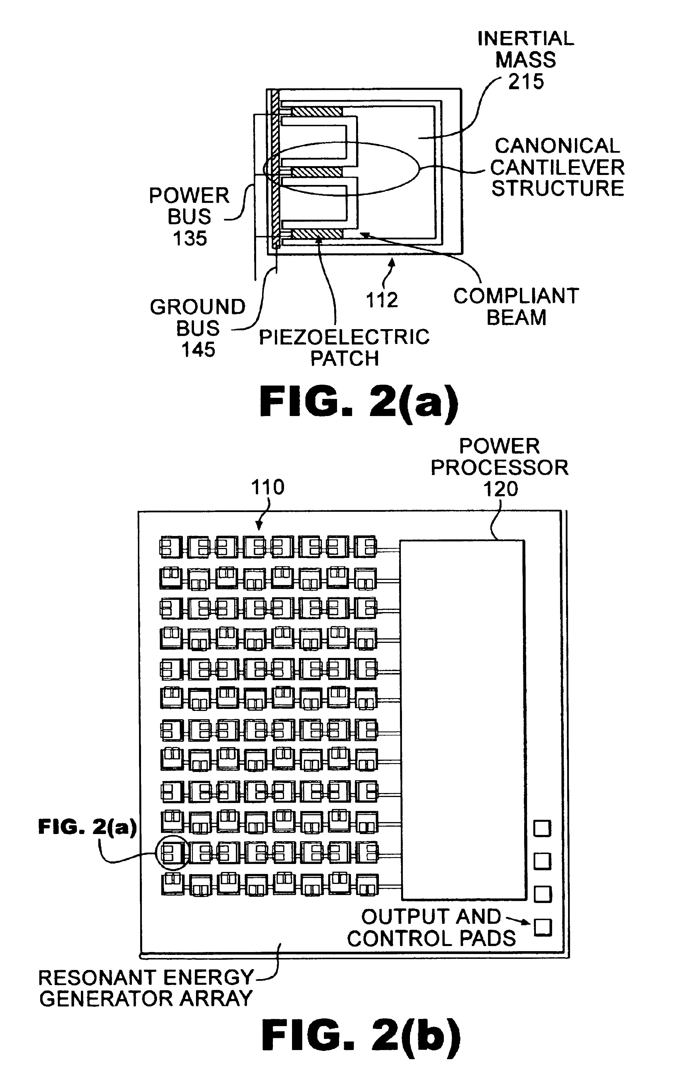
An integrated MEMS resonant generator system includes a substrate, a plurality of piezoelectric micro generators disposed on the substrate, the micro generators each generating a voltage output in response to vibrational energy received, and at least one power processor disposed on the substrate. The power processor electrically coupled to outputs of the plurality of micro generators. When the input conditions change, the power processor can dynamically adjust its switching functions to optimize the power delivered to a load or energy storage reservoir.

Description

CROSS-REFERENCE TO RELATED APPLICATIONS[0001]This application claims priority to the U.S. provisional application No. 60 / 380,187 filed May 13, 2002, which is incorporated herein by reference in its entirety.STATEMENT REGARDING FEDERALLY SPONSORED RESEARCH OR DEVELOPMENT[0002]The United States Government has rights in this invention pursuant to Grant No. N00014 99 1 0450 between the Office of Naval Research and the University of Florida.FIELD OF THE INVENTION[0003]The invention relates to power generators, more particularly, to self powered microsystem generators.BACKGROUND[0004]Over the years there has been a growing interest in the field of miniature sensors. Applications for miniature sensors are wide ranging and include medical implants and embedded sensors in buildings. One specific area that has received little attention is how to supply the required electrical power to such sensors. Conventional power supplies, such as batteries, can be disposed external to such sensors. Howev...

Claims


Application Information

Patent Timeline
IPC IPC(8): H01L27/20H01L41/113H01L41/00H01L41/04H02N2/18
CPCH01L27/20H02N2/181H02N2/188H10N39/00
Inventor NISHIDA, TOSHIKAZUCATTAFESTA, III, LOUIS N.SHEPLAK, MARKNGO, KHAI D. T.
Owner UNIV OF FLORIDA RES FOUNDATION INC
Learn More