
Database load balancing for multi-tier computer systems

a database and load balancing technology, applied in the field of database systems, can solve the problems of reducing system availability and performance, affecting the performance of the system, and not being able to adapt to changing environments and scaling with increasing user and data volume and traffic, so as to maximize server efficiency, optimize resource utilization, and avoid the effect of system failures

Inactive Publication Date: 2005-09-27
YOUSEFIZADEH HOMAYOUN
View PDF9 Cites 439 Cited by
  • Summary
  • Abstract
  • Description
  • Claims
  • Application Information

AI Technical Summary

Benefits of technology

[0009]The present invention alleviates the shortcomings of conventional systems. In one embodiment, the present invention provides implementation independent database load balancing for a scalable computer system comprising networked client and server computers, to maximize server efficiency. Dynamic load balancing optimizes the resource utilization to reduce server response times, such as in database management systems.

Problems solved by technology

A disadvantage of the two-tier architecture is that it is not capable of adapting to changing environments and scaling with growing user and data volume and traffic.
However, a major disadvantage of such a system is that a relatively large number of clients in the first tier simultaneously requesting remote services can gradually create a bottleneck in the second and third tiers.
This degrades system availability and performance.
Though the performance shortcomings of the middle layer tier are somewhat alleviated, the back-end database tier continues to suffer substantially from lack of load-balancing, lack of scalability and performance enhancements, thereby negatively impacting the availability and scalability of the entire multi-tier system.

Method used


Image

  • Database load balancing for multi-tier computer systems
  • Database load balancing for multi-tier computer systems
  • Database load balancing for multi-tier computer systems

Examples


Embodiment Construction

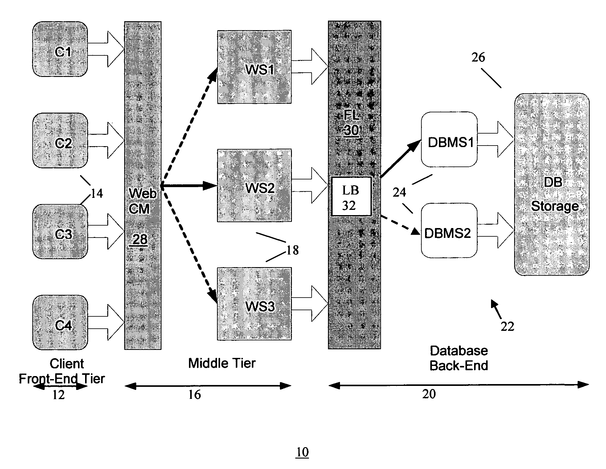
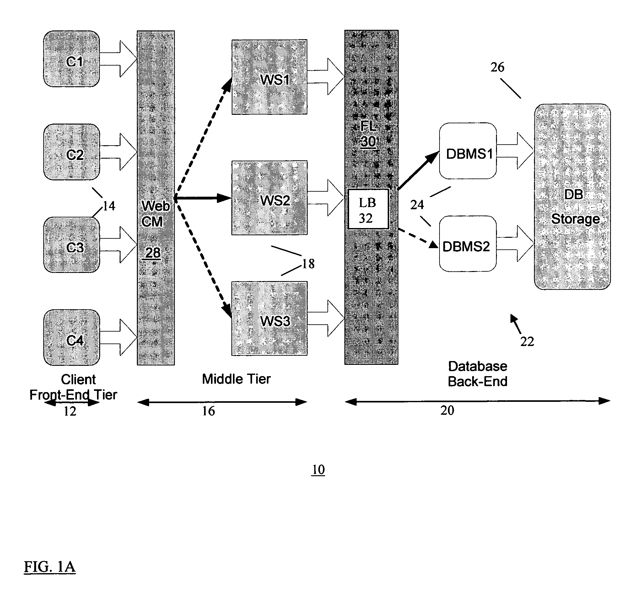
[0030]FIG. 1A shows an example architectural block diagram of an embodiment of a multi-tier network computer system 10 according to the present invention. The computer system comprises a three-tier architecture system including a front-end tier (first tier) 12 having multiple client workstations (clients) 14 (e.g., C1, C2, C3, C4), a middle-tier (second tier) 16 including servers 18 for data processing, and back-end tier (third tier) 20 including resources such a database system 22. The middle tier 16 (e.g., application server) provides data processing and interface between the front-end tier 12 (client) and the back-end tier 20. The middle tier 16 comprises the primary interface interacting with the clients 14 located in the first tier 12, and hiding all of the functional details of the back-end tier 20 from the clients 14.

[0031]In the example three-tier architecture 10, each server 18 in the middle tier 16 comprises a Web server (e.g., WS1, WS2, WS3) that interact with Web browser...


PUM


Abstract

A load balancing method and system for a transaction computer system having multiple database servers for at least one database, wherein database servers cooperate to provide a unified view of the data in the database. The method includes the steps of establishing connections to said multiple database servers for communicating with said database servers; and assigning transactions to respective ones of said multiple database servers to balance respective loads of said multiple database servers. Assigning each new transaction includes the steps of determining possible assignments of that new transaction to one or more of said multiple database servers, each said possible assignment to one of said multiple database servers being based on a load balancing scheme to balance respective loads of said multiple database servers; and assigning that new transaction to one of said multiple database servers as a function of said possible assignments of that new transaction, to balance respective loads of said multiple database servers.

Description

FIELD OF THE INVENTION[0001]The present invention relates generally to database systems, and in particular to load balancing for database systems.BACKGROUND OF THE INVENTION[0002]Database systems are utilized in many aspects of data processing systems, including in networked computer systems such as the Internet and the World Wide Web (WWW) which have grown to a robust infrastructure for handling mission-critical business traffic. As the result, commerce on the Internet is growing exponentially with the increasing number of Web sites (servers) and Internet users using client workstations (client). To support this growth, Web sites (implemented on Web and database servers) must be able to set up and maintain a few million connections every second. Further, quick response time and continuous availability are mandatory requirements as Web sites compete to offer users the best on-line experience.[0003]Conventional networked computer infrastructure for businesses (e.g., over the Internet...

Claims


Application Information

Patent Timeline
IPC IPC(8): G06F15/16G06F9/50H04L29/06H04L29/08
CPCG06F9/50G06F9/505H04L67/1008H04L67/1036H04L67/101H04L67/14H04L67/02H04L67/1002H04L67/1017H04L67/1001
Inventor YOUSEFI'ZADEH, HOMAYOUN
Owner YOUSEFIZADEH HOMAYOUN
Learn More