
Pen-type electrosurgical instrument

Inactive Publication Date: 2005-09-27
MEDTRONIC INC
View PDF99 Cites 169 Cited by
  • Summary
  • Abstract
  • Description
  • Claims
  • Application Information

AI Technical Summary

Benefits of technology

[0014]In accordance with one aspect of the invention, the electrocautery electrode / tip is implemented with a hollow, conductive tube terminating at its distal end in a ball point type tip. Conductive fluid is applied to the proximal end of the hollow electrode / tip, and expelled from the distal end thereof during electrocautery. The ball point distal tip allows the distal tip to be directly applied to the tissue and “rolled” or slid along the tissue. This allows the distal tip to be moved across the tissue without dragging or snagging on the tissue. In addition, the conductive fluid expelled from the distal tip further lubricates the distal tip as it moves across the tissue.
[0015]In accordance with another aspect of the invention, the conductive fluid emanating from the electrode / tip conducts the RF electrocautery energy away from the distal tip so that it is primarily the fluid, rather than the distal tip that actually accomplishes the cauterizing of tissue. That is, the fluid serves as a “virtual” electrocautery electrode. Since it is the fluid, rather than the distal tip that cauterizes, coagulates and abates, no burns or perforations are made to the tissue, reducing the amount of debris at the site of ablation. Also, the flow of fluid through the electrode / tip tends to keep the distal tip clean and cool.

Problems solved by technology

It is widely recognized in the prior art that the often substantial amount of smoke produced by electrocauterization of tissue is at least unpleasant, and in some cases distracting or even hazardous to the operator and other attending medical personnel.
It has also been recognized in the prior art that the accumulation of coagulated blood, tissue rubble, and other debris on the electrode / tip of an electrocautery device can present a problem for the operator, necessitating the periodic cleaning of the tip, e.g., by wiping the tip over sterilized gauze or the like.
This is generally regarded as undesirable, since the need to clean the electrode / tip tends to interrupt the incision procedure and increases the risks associated with contamination of the tip or the incision, damage to the tip, injury to the operator, and the like.
There are at least three detrimental side effects that occur during atrial fibrillation: a rapid irregular heartbeat; impaired cardiac hemodynamics due to a loss of AV synchrony; and an increased vulnerability to thromboembolism.
For most patients with atrial fibrillation, this therapy has been only moderately effective and has typically produced undesirable side effects.
Although radiofrequency catheter ablation (RFCA) has proven to be a safe and effective way of treating the most benign causes of supraventricular tachycardia (SVT), such as Wolff-Parkinson-White and AV nodal re-entry tachycardia, using ablation to treat atrial fibrillation has proven to be challenging.
A problem with the “maze” procedure is that it requires open chest surgery which is undesirable.
However, it has also been recognized that current ablation technology has not developed to allow the “maze” procedure to be duplicated with ablation.
A problem with prior art ablation has been that the ablating tip, if left in contact with a piece of tissue for too long, will bum through and perforate the tissue.
In many applications, it has proven difficult to balance leaving an ablating tip in position on a piece of tissue for a sufficient time to allow the tissue to be ablated but not leave it in place for a length of time to burn through and thereby perforate the tissue.
Another problem with prior art ablation devices is that if the ablating tips are left in contact with the tissue too long, the tip “sticks” to the tissue being ablated.
This is not only a result to be avoided because of the tissue damage, but it is time consuming and irritating to the physician.

Method used


Image

  • Pen-type electrosurgical instrument
  • Pen-type electrosurgical instrument
  • Pen-type electrosurgical instrument

Examples


Embodiment Construction

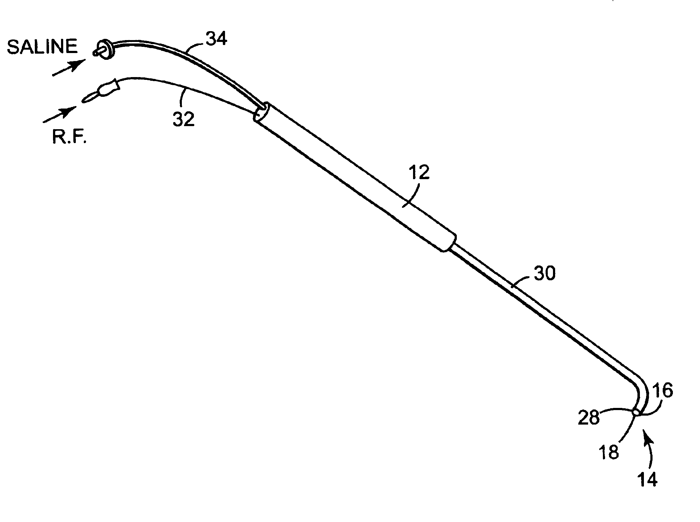
[0022]Referring to FIG. 1, there is shown a perspective view of a fluid-assisted electrocautery device 10 in accordance with one embodiment of the invention. Electrocautery device 10 comprises a handle 12 and an electrocautery electrode / tip 14. Handle 12 is preferably made of a sterilizable, rigid, and non-conductive material, such as nylon or the like. Electrode / tip 14 is attached to handle 12.

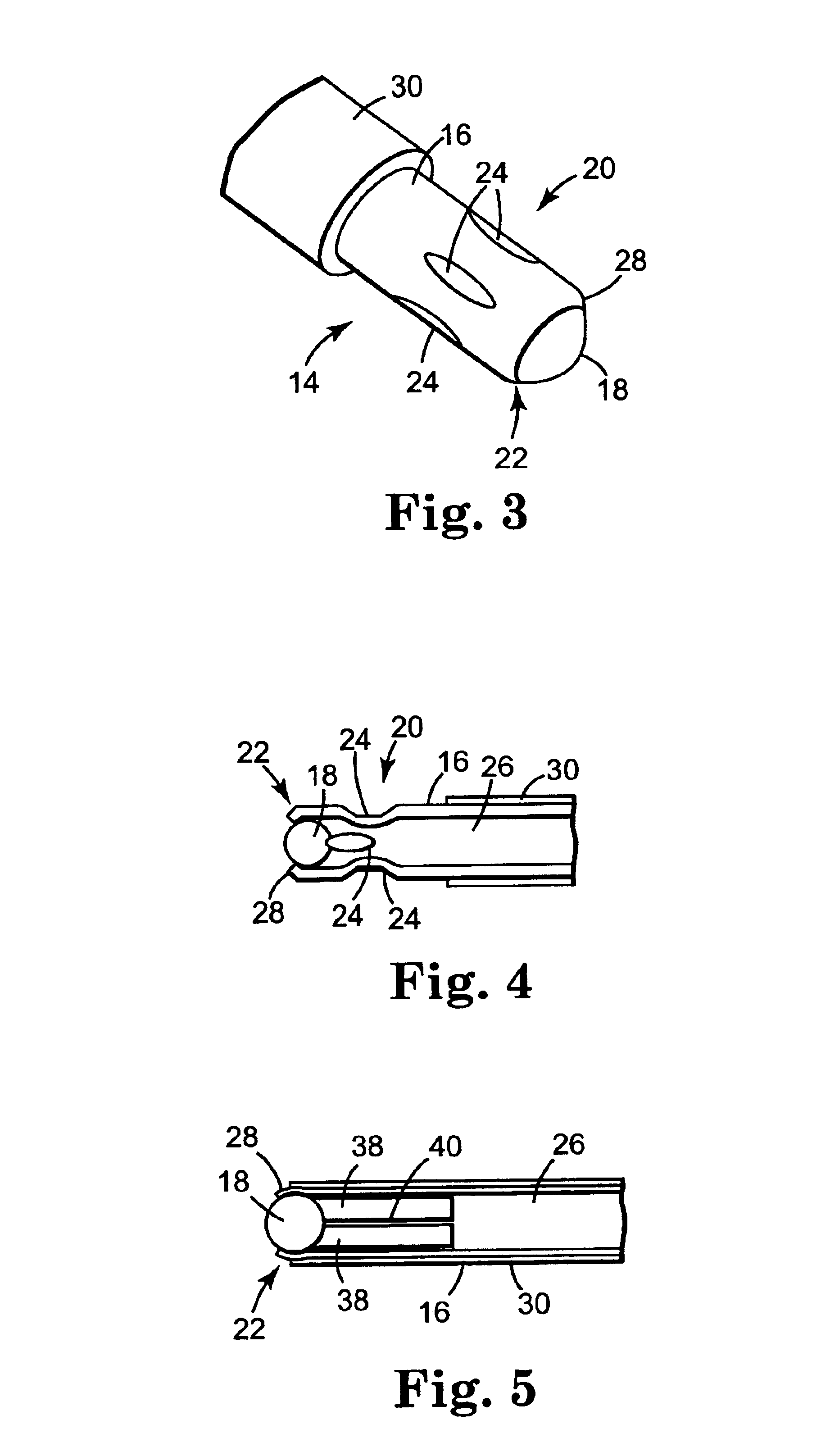
[0023]In accordance with one aspect of the invention, electrode / tip 14 is preferably implemented using a hollow cylindrical tube 16 with a “ball point” at its distal end, as shown in the greatly enlarged perspective and cross-sectional views of FIGS. 3 and 4, respectively. As can be seen, a ball 18 is retained in a cavity formed by crimping metal tube 16 around ball 18. Both ball 18 and tube 16 are preferably made of an electrically conductive metal such as stainless steel. Tube 16 is crimped both proximal and distal to ball 18 at 20 and 22, respectively.

[0024]Ball 18 may have any diameter bu...


PUM


Abstract

An electrocautery device is disclosed. In accordance with one aspect of the invention, the electrocautery electrode / tip is provided with a hollow, conductive tube terminating at its distal end in a ball point type tip. Fluid, preferably conductive fluid, is applied to the proximal end of the hollow electrode / tip, and expelled from the distal end thereof during electrocautery. The ball point distal tip allows the distal tip to be directly applied to the tissue and “rolled” or slid along the tissue. This allows the distal tip to be moved across the tissue without dragging or snagging on the tissue. In addition, the conductive fluid expelled from the distal tip further lubricates the distal tip as it moves across the tissue. If conductive fluid is used, the conductive fluid emanating from the electrode / tip conducts the RF electrocautery energy away from the distal tip so that it is primarily the fluid, rather than the distal tip that actually accomplishes the cauterizing of tissue. That is, the fluid serves as a “virtual” electrocautery electrode. Since it is the fluid, rather than the distal tip that cauterizes, coagulates and ablates, no burns or perforations are made to the tissue, reducing the amount of debris at the site. Also, the flow of fluid through the electrode / tip tends to keep the distal tip clean and cool.

Description

CROSS-REFERENCE TO RELATED APPLICATIONS[0001]This application is a continuation of U.S. patent application Ser. No. 10 / 411,921, filed Apr. 11, 2003, now U.S. Pat. No. 6,764,487 which is a continuation of U.S. patent application Ser. No. 09 / 955,496, filed Sep. 18, 2001, now U.S. Pat. No. 6,585,732, which is a continuation of U.S. patent application Ser. No. 09 / 580,228, filed May. 26, 2000, now U.S. Pat. No. 6,358,248, which is a continuation of U.S. patent application Ser. No. 09 / 236,034, filed Jan. 22, 1999, now abandoned, which is a continuation of U.S. patent application Ser. No. 08 / 556,784, filed Nov. 2, 1995, now U.S. Pat. No. 5,897,553, which is a continuation-in-part of U.S. patent application Ser. No. 08 / 393,082, filed Feb. 22, 1995, now U.S. Pat. No. 6,063,081, which applications are incorporated herein by reference.FIELD OF THE INVENTION[0002]This invention relates generally to the field of medical instruments, and more particularly relates to an electrocautery device.BACKG...

Claims


Application Information

Patent Timeline
IPC IPC(8): A61B18/14A61B18/00A61B18/12A61B18/08
CPCA61B18/1402A61M3/0279A61B18/1815A61B2018/00196A61B2018/00291A61B2018/1253A61B2018/1417A61B2018/1472A61B2018/1475A61B2018/1861A61B2218/002A61B2218/007
Inventor MULIER, PETER M. J.HOEY, MICHAEL F.
Owner MEDTRONIC INC
Learn More