
Furnace head or furnace throat seal

Inactive Publication Date: 2005-09-27
Z & J TECH
View PDF27 Cites 5 Cited by
  • Summary
  • Abstract
  • Description
  • Claims
  • Application Information

AI Technical Summary

Benefits of technology

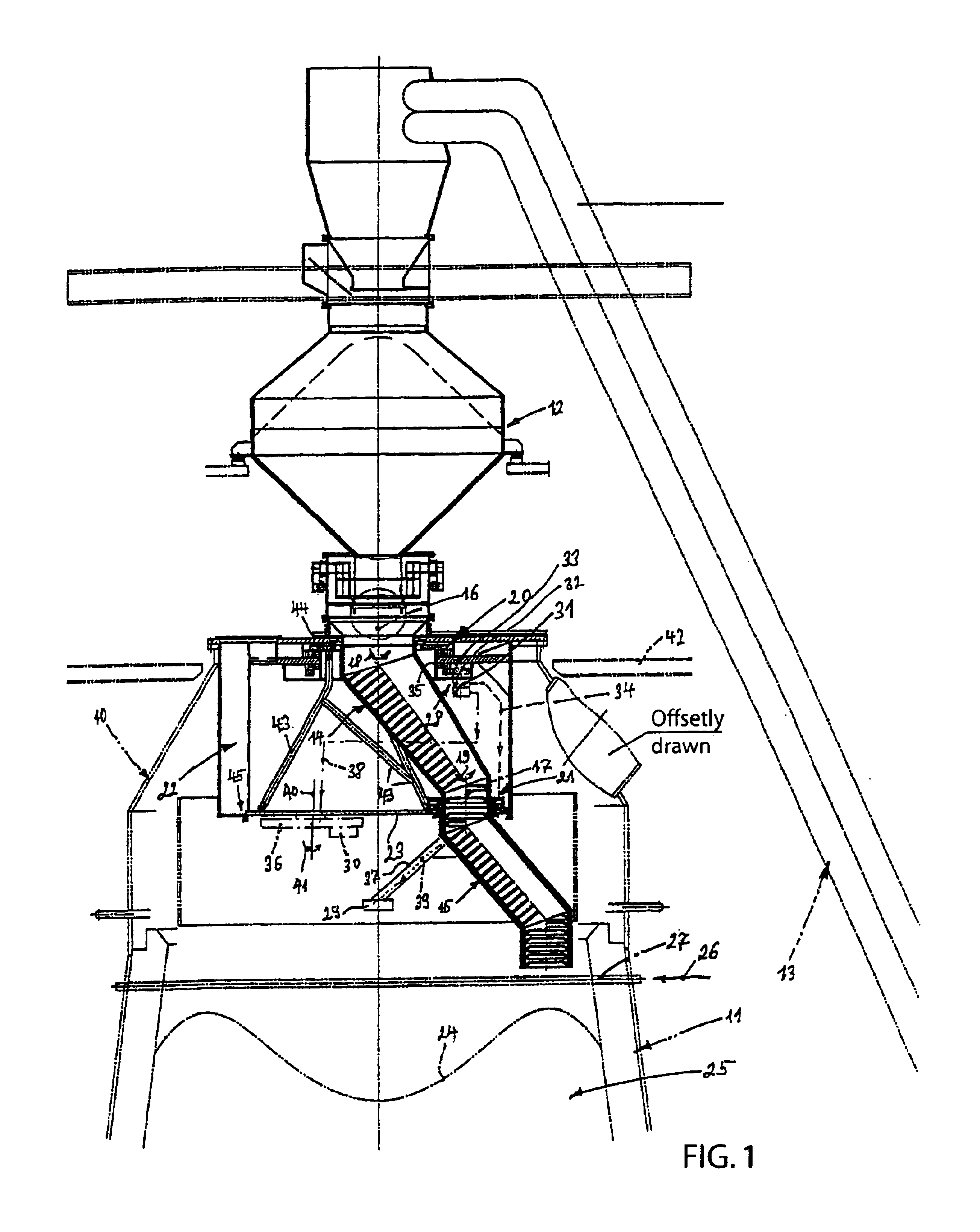
[0014]As an alternative, in an arrangement of a rotary and distributor chute or loading chute, the supply means may be driven by one of the gears assigned to the two chutes, in particular by the upper gear assigned to the rotary chute. The two gears assigned to the chutes, as well as the supply means are preferably situated inside of a dustproof and heatproof sealing chamber, thus ensuring an extremely compact and also functionally safe supply to measuring devices, lubrication points or similar over a long period. The supply means are either a dynamo supplying a measuring device with current and / or a lubricant pump supplying the two gears with lubricant, in particular the lower one assigned to the loading chute from the upper gear assigned to the rotary chute. Above all, the lubricant supply to the gear situated closer to the loading material or the lower gear is extremely critical due to the high temperatures prevailing there. Without an active lubricant supply, there would be a risk of the gear, as a rule a toothed gear, running dry and being subjected to increased wear and tear. Thanks to the lubricant supply of the invention, as well as the arrangement of the gear inside of a sealing chamber which ensures dust protection, the wear and tear of the gear may be considerably reduced resulting in a correspondingly longer lifetime. Here it has to be added that the sealing chamber is preferably acted upon by a flushing gas so as to ensure a dust-free zone within the chamber.
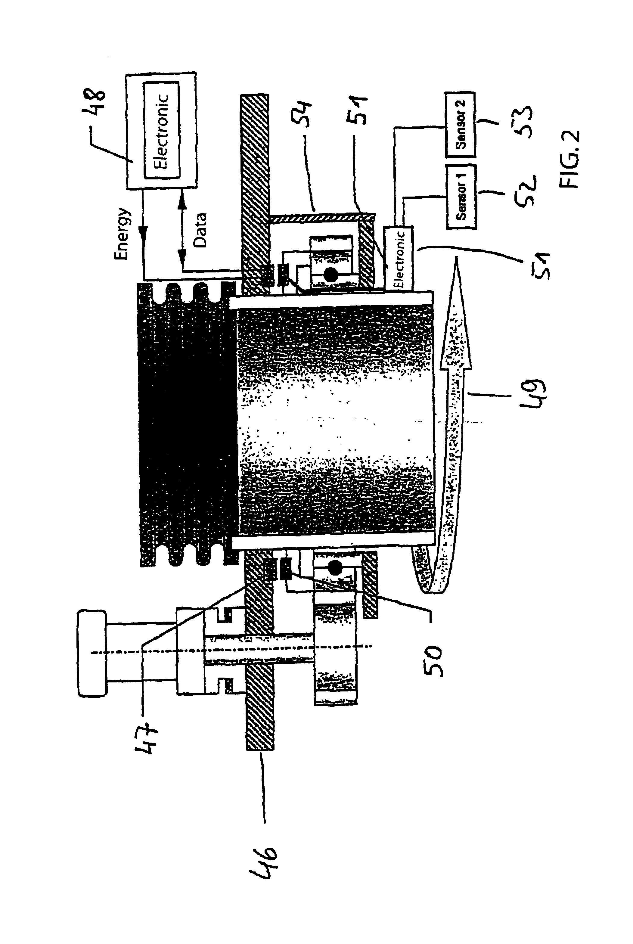
[0019]A particularly failsafe and wear-free energy supply of the measuring device, as well as a reliable data transfer is facilitated by a construction which transmits the required energy as well as the data by way of induction. Due to the fact that the transmission takes place contactless, a high resistance to interference may be achieved. With this construction, one can dispense with batteries and / or a generator or dynamo.

Problems solved by technology

Above all, the lubricant supply to the gear situated closer to the loading material or the lower gear is extremely critical due to the high temperatures prevailing there.
Without an active lubricant supply, there would be a risk of the gear, as a rule a toothed gear, running dry and being subjected to increased wear and tear.

Method used


Image

  • Furnace head or furnace throat seal
  • Furnace head or furnace throat seal
  • Furnace head or furnace throat seal

Examples


Embodiment Construction

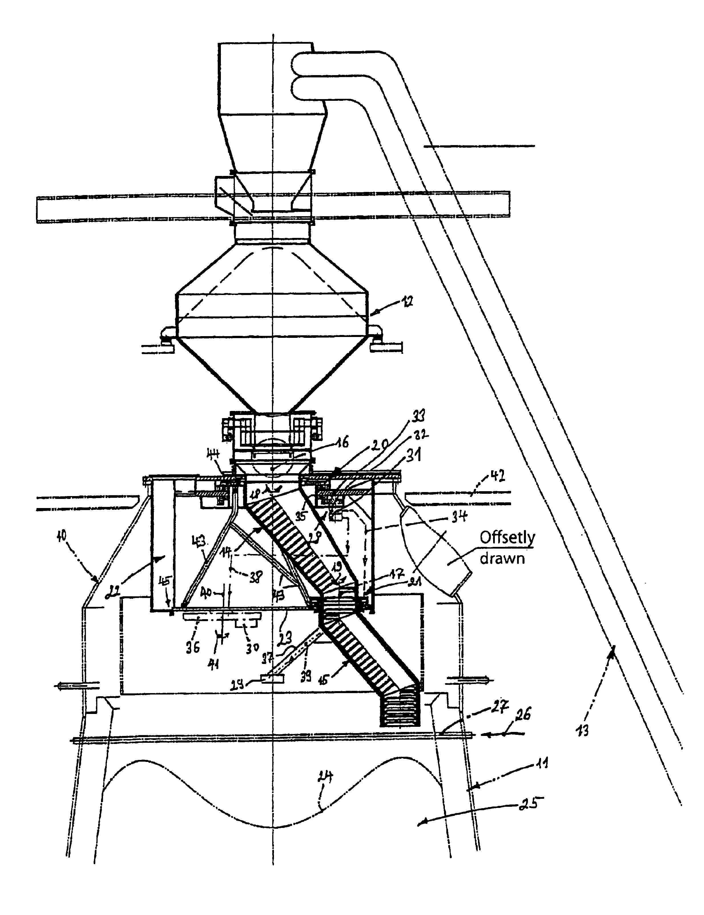
[0023]The furnace head is designated in the attached drawing by reference numeral 10. This furnace head is located above the furnace shell 11 or furnace throat of a blast furnace not shown in more detail. Above the furnace head, a so-called material bunker 12 is placed, into which a bulk material is filled via a conveying arrangement 13. From the material bunker 12 the loading of the furnace throat 11 via a rotary chute 14 and distributor or loading chute 15 then takes place. The rotary chute 14 is rotatingly driven about a first axis of rotation 16. At the outlet, i.e. at the lower end of the rotary chute 14, the distributor or loading chute is mounted driven in rotation about a second, vertical axis of rotation 17 laterally offset relative to the first axis of rotation 16. The respective rotary movements of the aforementioned chutes are indicated by the arrows 18, 19.

[0024]The rotary drive of both of the chutes 14, 15 is effectuated by assigned gears 20, 21 arranged within a cup-l...


PUM

PropertyMeasurementUnit
Temperatureaaaaaaaaaa
Pressureaaaaaaaaaa
Transmissionaaaaaaaaaa

Abstract

A blast furnace head (11) including a material loading device comprising rotary chute (14) driven in rotation about a first, vertical axis of rotation (16), and a loading chute (15) at the outlet of same, driven in rotation about a second, vertical axis of rotation (17) laterally offset relative to the first axis of rotation (16). The gears (20, 21) assigned to both of the chutes (14, 15) are arranged within a sealing chamber (22). Within this sealing chamber (22), a means (28) is arranged for supplying integrated measuring devices (29 or 30), lubrication points or similar maintenance recipients, with these supply means (28) being drivable by one of the gears (20, 21) assigned to the two chutes, in particular by the gear (20) assigned to the rotary chute (14).

Description

CROSS REFERENCE TO RELATED APPLICATION[0001]The present application claims priority from German Application No. 103 27 931.8 filed on Jun. 20, 2003 and German Application No. 103 34417.9 filed on Jul. 28, 2003.STATEMENT REGARDING FEDERALLY SPONSORED RESEARCH OR DEVELOPMENT[0002]Not ApplicableINCORPORATION-BY-REFERENCE OF MATERIAL SUBMITTED ON A COMPACT DISC[0003]Not ApplicableBACKGROUND OF THE INVENTION[0004]The invention relates to a furnace head or furnace throat seal according to the preamble of claim 1 or the preamble of claim 2.[0005]For loading (charging) shaft or blast furnaces with a charge, a plurality of various charging devices are known. In order to distribute the charge uniformly over the shaft cross-section, rotatable furnace throat seals including an equally rotatable distributor arranged eccentrically to the furnace axis were, in particular, already proposed decades ago. With such a charging device, a high degree of uniform loading may take place without formation of...

Claims


Application Information

Patent Timeline
IPC IPC(8): C21B7/18C21B7/20F27B1/20F27B1/26F27D3/00F27D3/10F27D19/00F27D21/00
CPCC21B7/20F27B1/20F27B1/26F27D3/0025F27D3/0032F27D3/0033F27D3/10F27D19/00F27D21/00C21B7/18
Inventor BRZOSKA, EKKEHARDIRNICH, FRANZ-JOSEFPAULUS, FRIEDHELM
Owner Z & J TECH
Learn More