
Optical recording medium, optical recording and reproducing method and apparatus

a recording medium and optical recording technology, applied in the field of optical recording and reproducing methods, optical recording mediums, optical recording/reproducing/erasing methods, instruments, etc., can solve the problems of physical limit of high-density optical recording, inconvenient recording density, optical disk, etc., and achieve the effect of stable s/n ratio

Inactive Publication Date: 2005-09-06
FUJIFILM BUSINESS INNOVATION CORP
View PDF23 Cites 22 Cited by
  • Summary
  • Abstract
  • Description
  • Claims
  • Application Information

AI Technical Summary

Benefits of technology

[0009]The present invention provides an optical recording medium and optical recording and reproducing method and apparatus in which multilevel data may be recorded and reproduced at a high density and with a high S / N ratio.
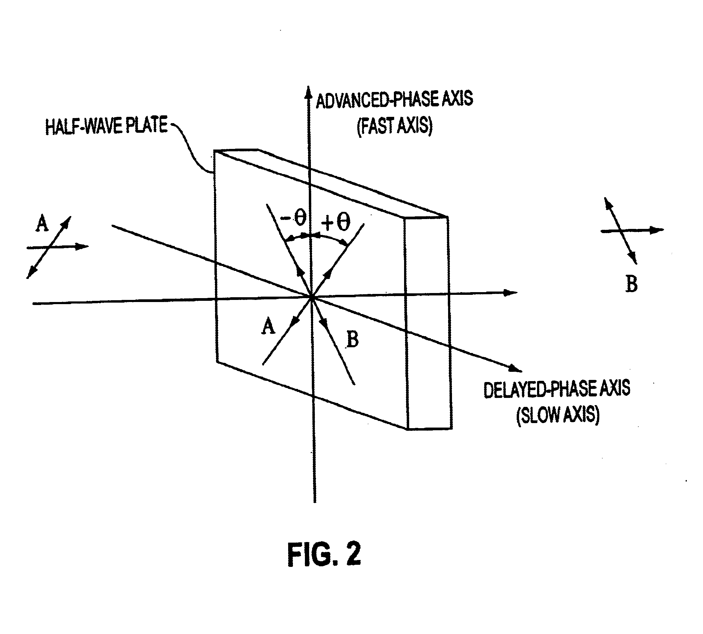
[0013]In an optical recording method according to the present invention, a birefringence is induced by directing linearly-polarized recording light to an optical recording medium to thereby form a half-wave plate or a quarter-wave plate having a polarization plane direction of the incident light. By rotating an azimuth (referred to as a polarization angle) of a polarization plane of the recording light, the azimuth of the half-wave plate or the quarter-wave plate is rotated. Accordingly, by making the polarization angle of the recording light multilevel, it is possible to perform multilevel recording.
[0017]According to the present invention, a high-density recording may be made by multilevel-modulating the polarization angle of the recording light. In addition, upon reproduction, the detected polarization angle is twice the angle of recording light so that a stable S / N ratio may be obtained.

Problems solved by technology

Although these optical disk apparatus are higher than ordinary magnetic disk apparatus in recording density by more than one order of magnitude, such recording density is not yet useful for recording digital image data.
However, on the other hand, since the above-mentioned optical disk records data within the surface, the optical disk is limited by diffraction so that a recording density of approximately 5 gigabits / inch2 is the physical limit of high-density optical recording.
However, although there are provided various devices, the change of the polarization angle obtained by the Kerr effect is very small, e.g. about 1 degree. As a result, it is difficult to provide multilevel data within this small polarization angle change from a Signal-to-Noise ratio (S / N) standpoint.
However, according to the typical manufacturing process for making a multilayer recording film, the number of the layers that can be laminated to provide the multilayer structure is limited, and the dynamic range cannot be widened.
Therefore, much of the multilevel-modulation cannot be obtained.
Also, there is then the problem that, when the film thickness of the recorded portion increases as the number of the layers in the multilayer increases, a recording density in the surface direction is lowered due to the diffusion of heat into the disk surface.
On the other hand, according to the method in which the recording pits are formed as elliptic recording pits, in order to keep a recording density similar to that of the conventional method, it is unavoidable that the area of the recording pits is decreased as compared with the ordinary case because the recording pits are formed in an elliptical shape.
As a result, it is not possible to avoid the signal intensity from being lowered in the single substance of the recording pit so that a deterioration in the S / N ratio occurs.
Therefore, if information is stored as multilevel information having a large number of different gradation levels, a lack of detection accuracy occurs.
Hence, multilevel information having a large number of gradation levels cannot be obtained.

Method used


Image

  • Optical recording medium, optical recording and reproducing method and apparatus
  • Optical recording medium, optical recording and reproducing method and apparatus
  • Optical recording medium, optical recording and reproducing method and apparatus

Examples


Embodiment Construction

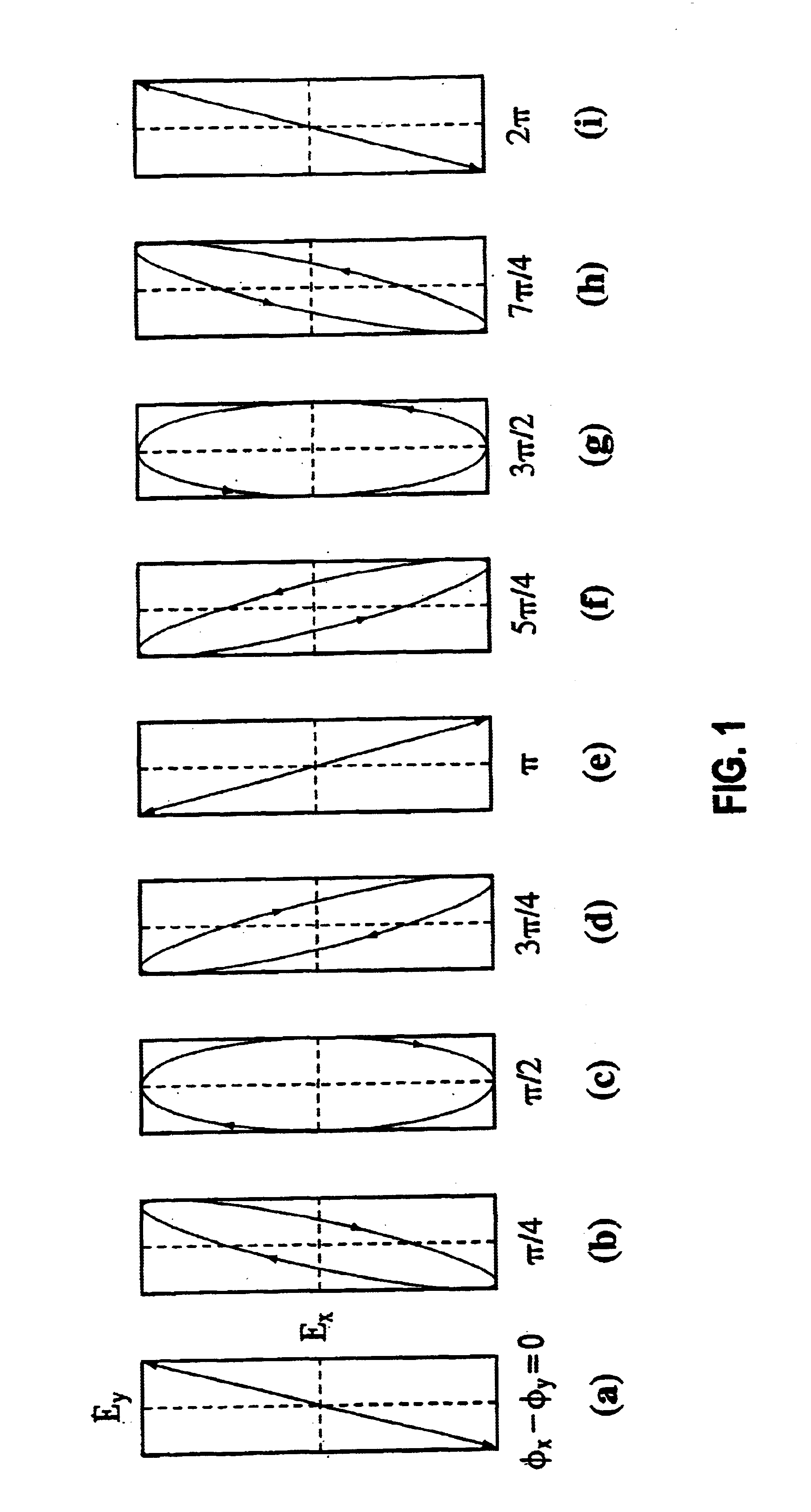
[0035]Initially, a principle of a polarization angle multilevel recording according to the present invention will be described. A method of rotating a polarization angle of linearly-polarized light at an arbitrary angle will be effected as follows. Light is a kind of electromagnetic wave and may be expressed by Maxwell's equations. If a z-axis (light traveling direction) is fixed, then the electromagnetic field E of light may be expressed by the following equation (1):

E(t)={circumflex over (x)}Ex cos(ωt−φx)+ŷEy cos(ωt−φy)  (1)

[0036]Here, φx and φy represent the initial phases relative to the x axis and y axis respectively. The tip end of this electric field vector E draws various orbits based on a value of a phase difference (φx−φy) between the x axis and the y axis. FIGS. 1(A) to 1(I) schematically show various orbits drawn by the tip end of the electric field E, and illustrate light polarized states obtained when the phase difference (φx−φy) between the x axis and the y axis is c...


PUM


Abstract

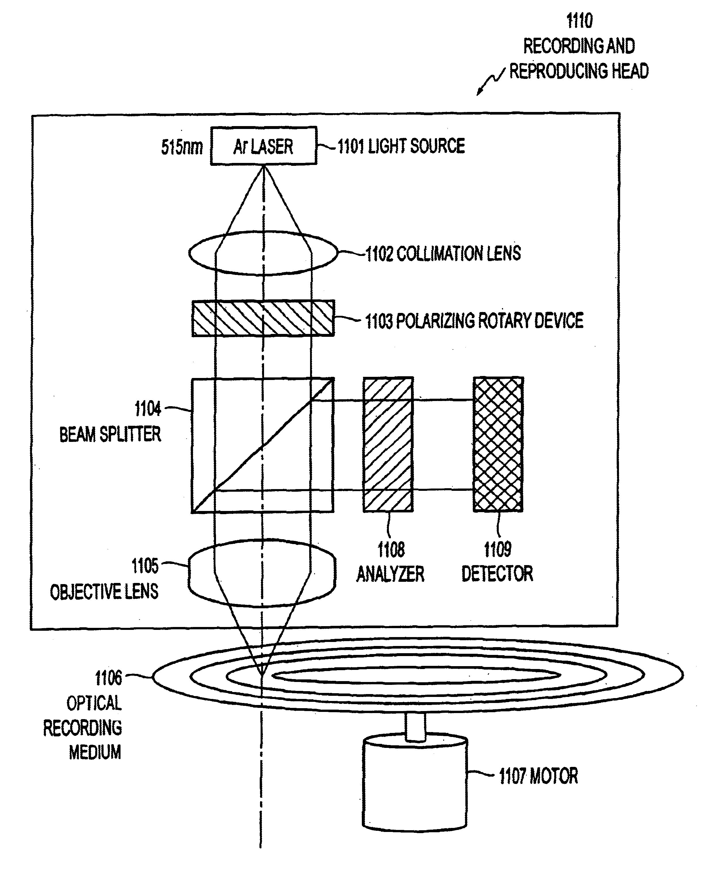
An optical recording medium, an optical recording and reproducing method, and an apparatus that can record and reproduce multilevel information at a high density and with a high S / N ratio. Recording light emitted from a light source is collimated by a collimation lens and introduced into a polarization rotary device. Recording light transmitted by the polarization rotary device is focused by an objective lens onto an optical recording medium. In response, a photo-induced birefringence is recorded on the optical recording medium. Multilevel recording is performed by controlling a voltage applied to the polarization rotary device to change a polarization angle θ of recording light. Reproduction is performed by detecting light reflected from the optical recording medium with an analyzer and a detector.

Description

BACKGROUND OF THE INVENTION[0001]1. Field of Invention[0002]The present invention relates to an optical recording medium, an optical recording and reproducing method, and an apparatus that realizes high density and high speed in data recording and data transferring, respectively.[0003]2. Description of Related Art[0004]In optical recording, rewritable optical disk apparatus such as a phase-change type and a magneto-optical disk type have heretofore been widely used for high-density recording. Although these optical disk apparatus are higher than ordinary magnetic disk apparatus in recording density by more than one order of magnitude, such recording density is not yet useful for recording digital image data. In order to further increase a recording density, it is necessary to reduce a distance between adjacent tracks or adjacent bits by reducing a diameter of a beam spot.[0005]A DVD-ROM that uses such optical recording technology is commercially available. The DVD-ROM is a 12-cm dis...

Claims


Application Information

Patent Timeline
IPC IPC(8): G11B7/00G11B7/12G11B7/135
CPCG11B7/0045G11B7/005G11B7/12G11B7/1398G11B7/2403G11B7/24088G11B7/245G11B7/2467G11B7/25G11B7/2531G11B7/2533G11B7/2585
Inventor ISHII, TSUTOMUKAWANO, KATSUNORIBABA, KAZUOUEYANAGI, KIICHI
Owner FUJIFILM BUSINESS INNOVATION CORP
Learn More