
Induction heat treatment method and coil and article treated thereby

a technology of induction heat treatment and coil and article, which is applied in the direction of electric/magnetic/electromagnetic heating, mechanical equipment, etc., can solve the problems of insufficient use of low torque handling capacity of housings, and inability to use induction hardening for various types of components, etc., to reduce the amount of grain growth or distortion, reduce the effect of heat treatment of the entire part and increase the strength of nodular cas

Inactive Publication Date: 2005-09-06
FORD GLOBAL TECH LLC
View PDF39 Cites 10 Cited by
  • Summary
  • Abstract
  • Description
  • Claims
  • Application Information

AI Technical Summary

Benefits of technology

This method significantly enhances the strength of nodular cast iron components by precisely hardening specific areas, minimizing distortion and reducing heat treatment costs, while maintaining component size and improving metallurgical and mechanical properties.

Problems solved by technology

However, the use of induction hardening for nodular iron components has been limited in cases where the portions of the component requiring heat treatment cannot be uniformly heated with an induction coil of conventional design, such as a cylindrical coil, perhaps due in part to the complex microstructural balances required as well as the difficulty associated with designing induction coils to provide the necessary heating of irregularly shaped surfaces.
While some solutions have been proposed to facilitate the use of induction hardening with articles having irregular surfaces, such as the use of different coils and different induction frequencies to treat different portions of the surface, or the use of coil designs that are adapted to the contour of the irregularities in order to provide more uniform inductive coupling, induction hardening has not been used for various types of components, such as those described below.
As these requirements are increased, Applicants have observed that they occasionally exceed the torque handling capacity of the housing, leading to fracture of the housing in the area having the lowest torque handling capacity.

Method used


Image

  • Induction heat treatment method and coil and article treated thereby
  • Induction heat treatment method and coil and article treated thereby
  • Induction heat treatment method and coil and article treated thereby

Examples


Embodiment Construction

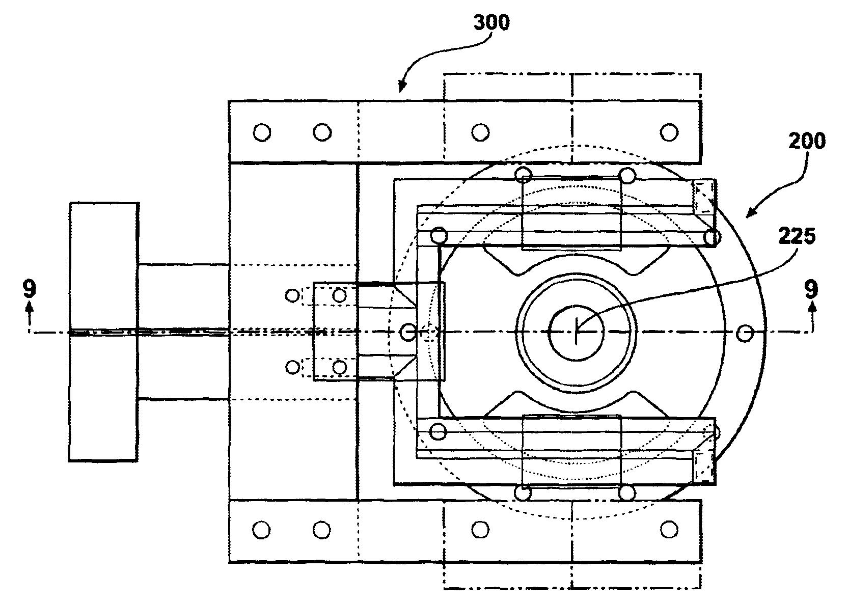
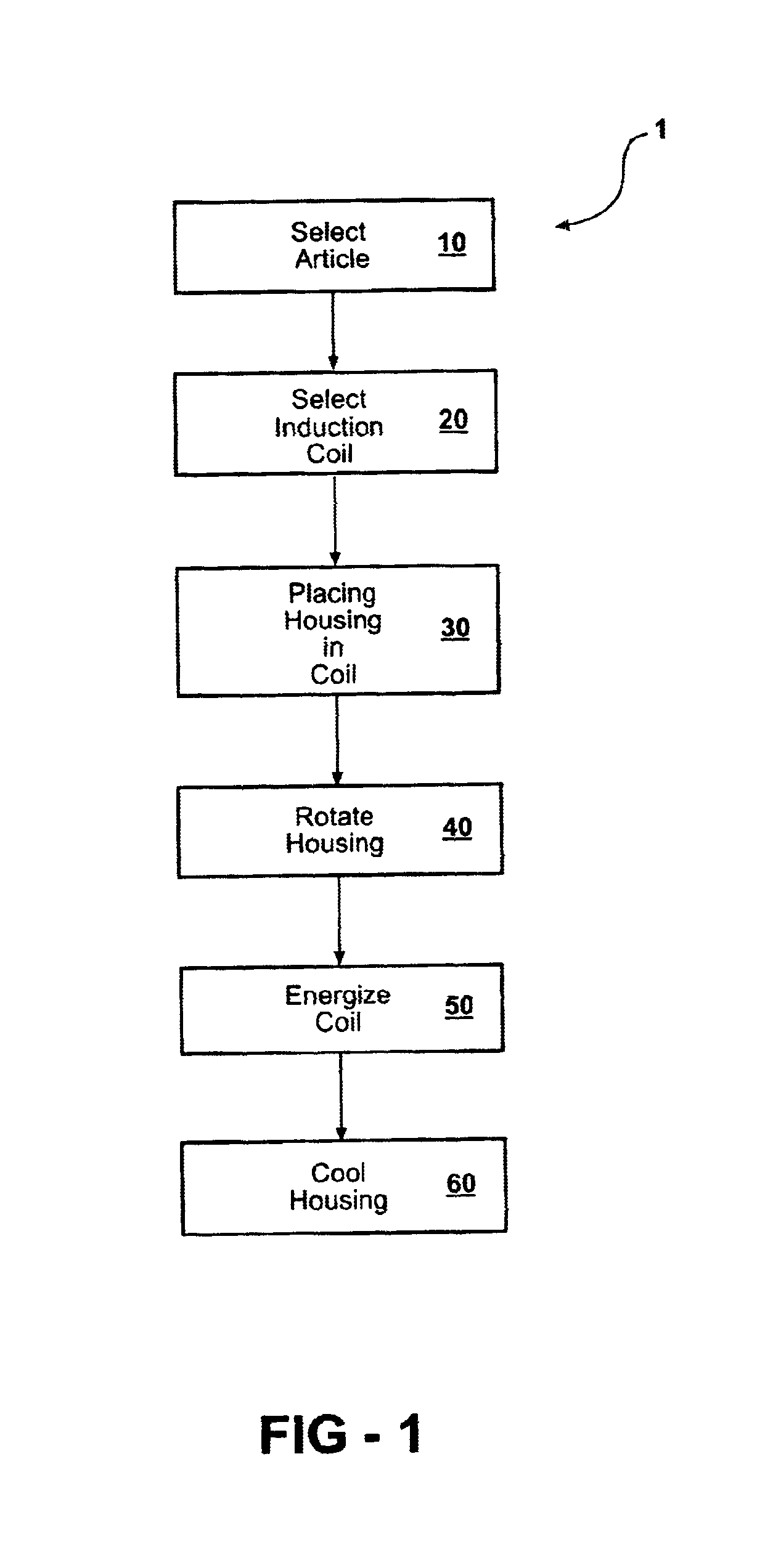
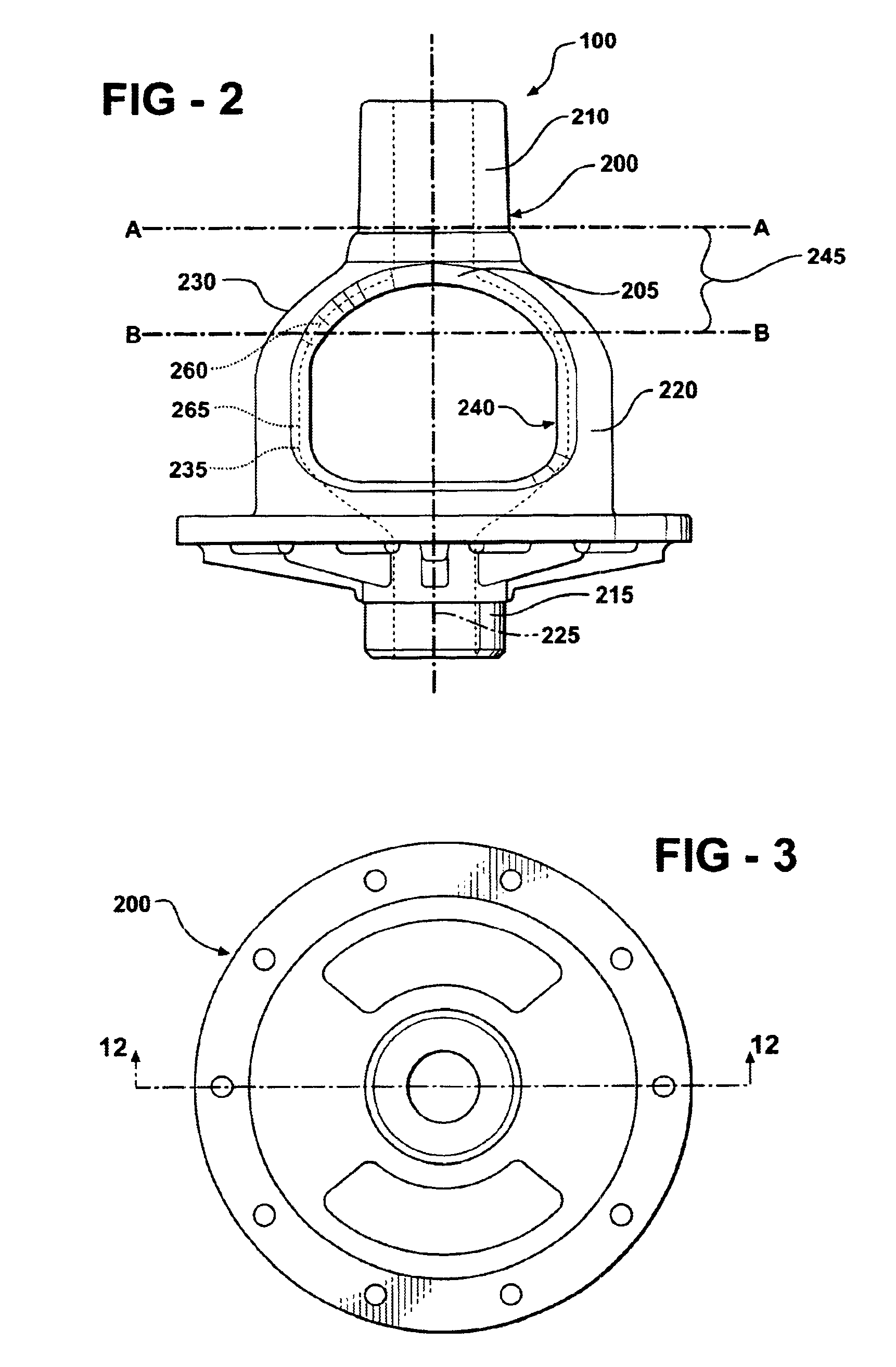
[0029]Referring to FIGS. 1-13, the present invention comprises a method 1 of induction heat treatment. Method 1 comprises the steps of: selecting 10 an article 100 for heat treatment, such as differential housing 200, comprising a metal wall 205 having an upper hub portion 210, a lower hub portion 215, a bell-shaped portion 220 that is located between the upper hub portion and the lower hub portion and a longitudinal axis 225 extending through each of the upper hub portion 210, lower hub portion 215 and bell-shaped portion 220, the bell-shaped portion 220 having a bell-shaped outer surface 230, an inner surface 235 and a plurality of windows 240 extending from the outer surface to the inner surface; selecting 20 an induction coil 300 comprising a hollow metal channel 305 having a first termination portion 310, a second termination portion 315 and a semi-rectangular inductor portion 320 that is operably connected to the first termination portion 310 and the second termination portion...


PUM

PropertyMeasurementUnit
frequencyaaaaaaaaaa
thicknessaaaaaaaaaa
outer heightaaaaaaaaaa

Abstract

A method of induction heat treatment of articles having curved outer surfaces, such as differential housings. The method employs a semi-rectangular induction coil that is adapted to provide a plurality of lateral magnetic fields that are used to induce currents in, and thereby provide heat to, a portion of the curved section of the article. The method and induction coil are particularly adapted to provide an induction hardening heat treatment of a curved heat treatment portion of a differential housing. The differential housing was cast from nodular iron. The induction-hardening heat treatment comprised heating the heat treatment portion of the differential housing above the austenite transition temperature and quenching to below the martensite transformation temperature.

Description

FIELD OF THE INVENTION[0001]The present invention relates to a method of induction heat treatment. More specifically, the invention comprises a method for induction hardening certain metal components, particularly those having a curved outer surface. Most particularly, the invention comprises a method for induction hardening a cast nodular iron differential housing.BACKGROUND OF THE INVENTION[0002]Induction heat treatment is known to be an effective method of case hardening certain nodular iron alloys. However, the use of induction hardening for nodular iron components has been limited in cases where the portions of the component requiring heat treatment cannot be uniformly heated with an induction coil of conventional design, such as a cylindrical coil, perhaps due in part to the complex microstructural balances required as well as the difficulty associated with designing induction coils to provide the necessary heating of irregularly shaped surfaces. While some solutions have been...

Claims


Application Information

Patent Timeline
Patent Type & Authority Patents(United States)
IPC IPC(8): C21D5/00C21D1/42H05B6/02H05B6/10
CPCC21D1/42C21D5/00C21D2221/00F16H48/08Y02P10/25
Inventor CHRISTOFIS, MARKCORLESS, REX R.KUMASHI, RAJENDRA G.MILLER, JR., WILLIAM R.SZALONY, NORMANSZCZOMAK, TED
Owner FORD GLOBAL TECH LLC
Learn More