
Method for fabrication of miniature lightweight antennas

a lightweight, miniature technology, applied in the direction of individually energised antenna arrays, flexible aerials, collapsible antenna means, etc., can solve the problems of increasing the cost of existing antennas, and increasing the cost of manufacturing existing antennas. , to achieve the effect of reducing the total cost of these antennas and devices, reducing the cost of material or assembly labor, and reducing the total cos

Inactive Publication Date: 2005-08-30
OAE TECH INC
View PDF5 Cites 48 Cited by
  • Summary
  • Abstract
  • Description
  • Claims
  • Application Information

AI Technical Summary

Benefits of technology

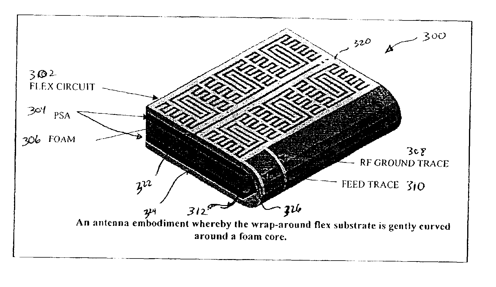
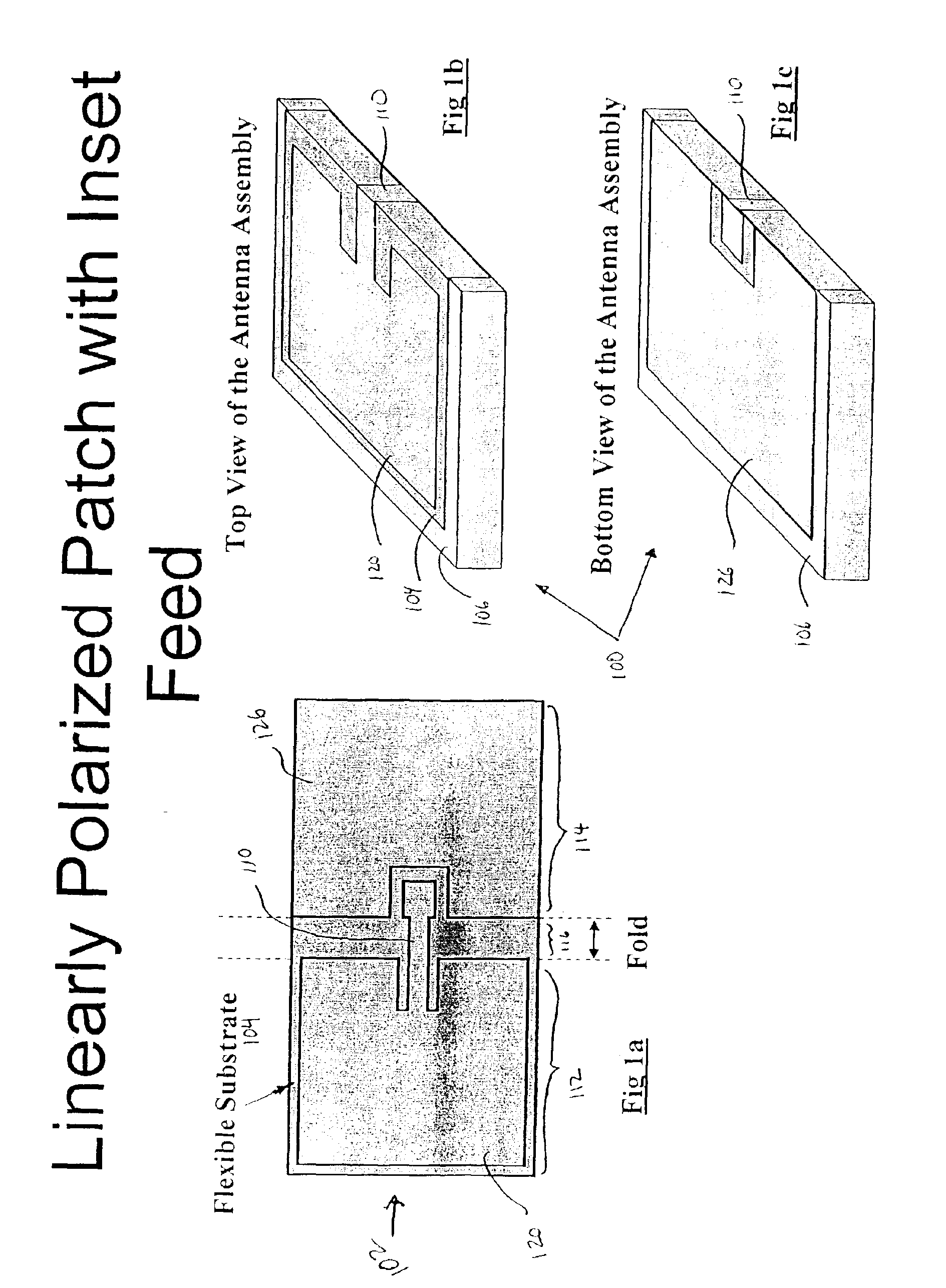
[0017]Additionally in this embodiment, the feed connector may extend from near a corner of the circuit pattern. The feed and ground connectors may extend from the circuit pattern along a first portion of the flex circuit through a second portion of the flex circuit substantially perpendicular to the first portion of the flex circuit to a third portion of the flex circuit substantially parallel with the first portion of the flex circuit. Sides of the substrate may be creased and folded to provide mechanical stability.

Problems solved by technology

Manufacturers of portable wireless devices such as handsets, personal digital assistants (PDA's) and laptops are constantly under extreme size and cost pressures.
All of these wireless devices typically pack a substantial amount of circuitry in a very small package, which requires one or more antenna to communicate.
However, existing antennas for similar frequencies of operation used to decrease the size of the device still require a relatively large amount of space and weight.
Furthermore, and most importantly, these existing antennas cost considerably more to manufacture than standard antennas.
The most common are external antennas, but these are quickly falling out of favor due to poor aesthetics and a high rate of needed repair and replacement.
Disadvantages of these types of internal antennas include both that the manufacturing cost is much higher and the bandwidth covered by the antennas is much less, i.e. the performance suffers greatly.
To date, however, none of the above antennas satisfy the present design goals, which specify efficient, compact, low profile antennas whose height is at most λ / 60 above a ground plane.

Method used


Image

  • Method for fabrication of miniature lightweight antennas
  • Method for fabrication of miniature lightweight antennas
  • Method for fabrication of miniature lightweight antennas

Examples


Embodiment Construction

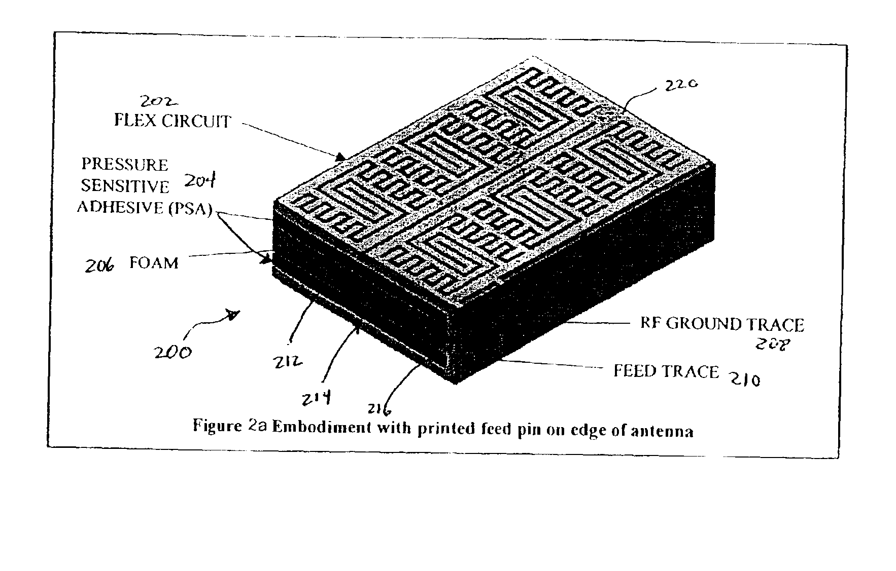
[0051]Many patents and publications exist on techniques used to create low cost portable antennas. However, as of this writing, we are not aware of any approaches that can achieve as low a cost solution with as high a level of performance in such a small volume and weight. Present embodiments illustrate multiple, related, low-cost approaches to manufacturing antennas. Specifically, the class of antennas these techniques target are those described in provisional patent applications entitled U.S. patent application Ser. Nos. 10 / 211,731 and 10 / 242,087 entitled “Miniature Reverse-Fed Planar Inverted F-Antenna,” and “DC Inductive Shorted Patch Antenna.” Many antenna prototypes have been manufactured using a flex (polyimide) or FR4 top layer on a foam core, connected to ground and feed port by soldered wires.

[0052]Besides the antennas having a small volume, low weight, low-cost and a high-level performance, some of the present embodiments also illustrate antennas that are integrated into ...


PUM


Abstract

Lightweight, small antennas are described that have decreased material and fabrication / processing cost. The antennas may be used in consumer electronics products such as cellular phones, laptops and PDA's. Some of the antennas and fabrication techniques also provide lower part count and increased reliability. All antennas are fabricated with standard materials currently available in high volume production.

Description

RELATED APPLICATIONS[0001]This application is related to U.S. Provisional Patent Application Ser. No. 60 / 310,655 filed Aug. 6, 2001 in the names of William E. McKinzie III, Greg S. Mendolia and Rodolfo E. Diaz and entitled “LOW FREQUENCY ENHANCED FREQUENCY SELECTIVE SURFACE TECHNOLOGY AND APPLICATIONS,” and U.S. Provisional Patent Application Nos. 60 / 354,003 and 60 / 352,113 filed Jan. 23, 2002 in the names of Greg S. Mendolia, John Dutton and William E. McKinzie III and entitled “MINIATURIZED REVERSE-FED PLANAR INVERTED-F ANTENNA,” and “DC INDUCTIVE SHORTED PATCH ANTENNA,” all of which are incorporated herein by reference in their entirety.BACKGROUND[0002]This invention relates to antennas and devices incorporating antennas. In particular, this invention relates to low cost miniature antennas for lightweight products that are very reproducible in high volumes and whose electrical characteristics are very repeatable.[0003]Manufacturers of portable wireless devices such as handsets, pe...

Claims


Application Information

Patent Timeline
IPC IPC(8): H01Q1/38H01Q9/04H01Q1/08H01Q1/24H01Q21/08
CPCH01Q1/085H01Q1/241H01Q1/38H01Q9/0407H01Q9/0428H01Q9/0471H01Q21/08
Inventor MENDOLIA, GREGORY S.MCKINZIE, III, WILLIAM E.DUTTON, JOHN
Owner OAE TECH INC
Learn More