
Magnetic field and electrical current visualization system

a technology of electromagnetic field and electrical current, applied in non-linear optics, instruments, optics, etc., can solve the problems of mr sensor-based instruments not always providing the requisite spatial resolution and speed, and the cost of known squid microscopes is generally high

Inactive Publication Date: 2005-08-23
LAKE SHORE CRYOTRONICS INC
View PDF9 Cites 26 Cited by
  • Summary
  • Abstract
  • Description
  • Claims
  • Application Information

AI Technical Summary

Benefits of technology

The patent text describes a technique called magneto-optical imaging that uses special films to visualize magnetic fields or currents. This technique offers high resolution and sensitivity, but current methods have limitations in terms of speed and dynamic range. The patent proposes a new approach that overcomes these limitations and offers better magnetic field and current resolution, as well as faster imaging and better dynamic range. The technique uses iron garnet films with perpendicular magnetic anisotropies, which offer higher magnetic field sensitivity and better magnetic field resolution compared to other films. The patent also describes the use of magneto-optical visualizers in various applications, such as non-destructive testing and imaging of permanent magnets.

Problems solved by technology

However, known SQUID microscopes are generally expensive, slow and relatively limited in spatial resolution (e.g., currently limited to about 20-50 μm when imaging objects at room temperature).
However, MR sensor-based instruments don't always provide the requisite spatial resolution and speed.
MFM offers superior spatial resolution but can be extremely slow, especially when visualizing large areas.
In addition, the dynamic range and magnetic field and / or electrical current resolution of magnetic force microscopes are often limited.
However, in general, such instruments currently have relatively limited magnetic field dynamic range and low-field visualization.
Such specific properties can be difficult to satisfy at a single temperature and virtually impossible to satisfy over a wide temperature range.
However, limited polarization rotation can limit magnetic field resolution and dynamic range of the Kerr microscope instrument.
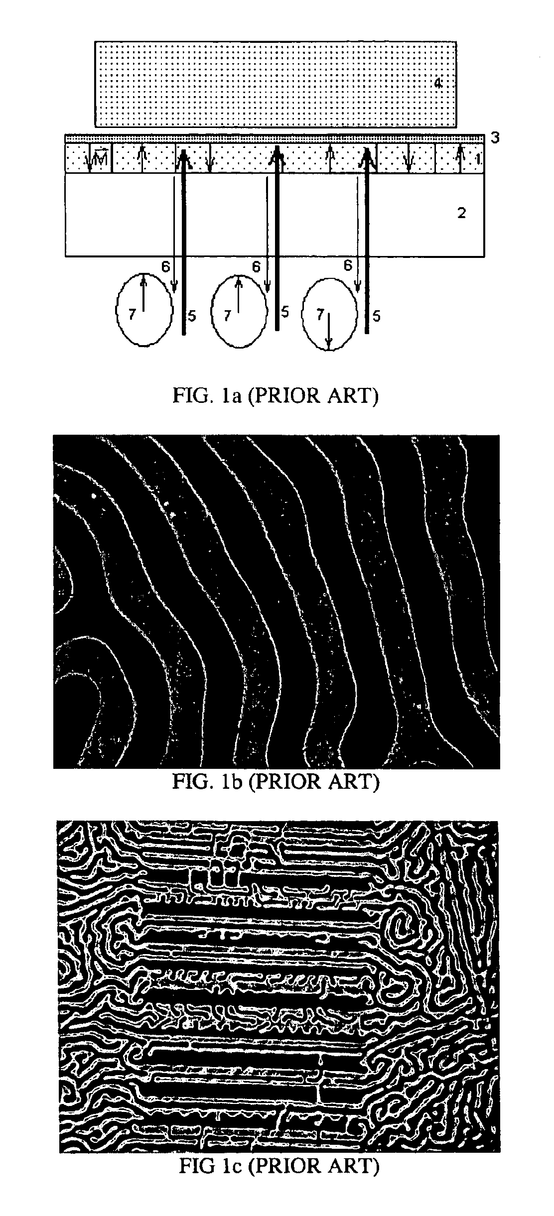
However, the perpendicular films can be limited in both spatial and magnetic field resolutions (see FIG. 1c).
However, there have been certain disadvantages in using in-plane films in the prior art, although it should be noted that disadvantages are different for different disclosed arrangements.
2B), April 1996 p.6073] and in U.S. Pat. No. 6,141,093 to Argyle, et al., one problem is the difficulty of achieving good enough collimation of polychromatic light from the visualizer's illuminator P1 to provide enough extinction between crossed polarizers.
This often results in background noise and a low dynamic range of the visualizer.
In addition, variations in microscope illumination intensity and spectral distribution of the emitted light (e.g., due to heating or other effects) may cause a stability problem in this type of visualizer, possibly requiring frequent recalibration and decreasing long-term accuracy.
Laser illumination provides certain advantages but can cause parasitic interference and speckle patterns due to the long coherence length of laser source.
However, these arrangements require relatively complicated and expensive mechanics to perform scans over a whole wafer.
In addition, even though the dynamic range and magnetic field resolution achievable with such visualizers may exceed that of the other prior art visualizer designs, the dynamic range and magnetic field resolution may be limited at low magnetic fields.
With the collapse of the magnetic bubble industry, much of the accumulated YIG-growing skills and expertise are beginning to be lost.
Unfortunately, this limits the penetration of such a technique into many high-volume markets, such as IC (integrated circuit) current visualization.

Method used


Image

  • Magnetic field and electrical current visualization system
  • Magnetic field and electrical current visualization system
  • Magnetic field and electrical current visualization system

Examples


example 3d

[0136 plots of numerically calculated magnetic energy in different (111) iron garnets are given in FIGS. 10a and 10b. FIG. 10a shows the easy axes tilted with respect to the plane of the film and the hard axes slightly tilted from the (100), (010) and (001) directions. This is the case of pure cubic anisotropy. Another common type of magnetic anisotropy in thin film YIGs is shown in FIG. 10b, where a single easy axis lies in the plane or close to the plane of the film. Such an anisotropy may be preferred for MOIF structures used in the different embodiments. An exemplary experimental plot of the magnetic moment of such a film as a function of the applied perpendicular field is presented in FIG. 10c. Example plots of Faraday rotation as a function of the in-plane magnetic field applied along the hard and easy axes are shown in FIG. 10d. The very low coercivity and two orders of magnitude difference in the in-plane hard axis and perpendicular saturation field are clearly illustrated.

[...


PUM

PropertyMeasurementUnit
angleaaaaaaaaaa
domain sizeaaaaaaaaaa
refractive indicesaaaaaaaaaa

Abstract

Magnetic field and / or electrical current imaging systems utilizing magneto-optical indicator films (MOIF) based on magneto-optical material with in-plane single easy axis type of magnetic anisotropy provide improved magnetic field resolution and dynamic range with the use of specific illumination conditions. Methods that provide the two-dimensional distribution of the external magnetic field vectors are disclosed together with the methods of extraction of said information. The visualizing systems offer high spatial resolution and / or high magnetic field resolution combined with fast sampling rates and the capability of performing large-area imaging. The applications of such systems include nondestructive testing and damage assessment in metal structures via magnetic materials or induced currents, integrated circuit testing and quality control, general magnetic material and thin film research, permanent magnet quality control, superconductor research and many others.

Description

CROSS-REFERENCES TO RELATED APPLICATIONS[0001]This application claims priority from provisional application Ser. No. 60 / 445,832 filed Feb. 10, 2003 entitled “Magnetic Field and Electrical Current Visualization System”.[0002]This application is related to U.S. patent application Ser. No. 10 / 764,496 filed Jan. 27, 2004 which claims priority from provisional application Ser. No. 60 / 442,539 filed Jan. 27, 2003 entitled “SURFACE CORRUGATION ENHANCED MAGNETO-OPTICAL INDICATOR FILM”.[0003]Each of the above-referenced patent specifications is incorporated herein by reference.FIELD[0004]The technology herein relates to magnetic field and / or electrical current imaging systems using magneto-optical indicator films (MOIF) based on magneto-optical material with the in-plane, single easy axis type of magnetic anisotropy. The technology herein also relates to the method of extraction of the distribution of three-dimensional magnetic field vectors in the said MOIF. The exemplary non-limiting visual...

Claims


Application Information

Patent Timeline
Patent Type & Authority Patents(United States)
IPC IPC(8): G02F1/09G02F1/01
CPCG02F1/09
Inventor KOCHERGIN, VLADIMIR
Owner LAKE SHORE CRYOTRONICS INC
Learn More