Perpendicular magnetic recording medium and magnetic storage apparatus

Inactive Publication Date: 2005-08-09
WESTERN DIGITAL TECH INC +1
View PDF17 Cites 10 Cited by
  • Summary
  • Abstract
  • Description
  • Claims
  • Application Information

AI Technical Summary

Benefits of technology

[0009]An object of the present invention is to provide a perpendicular magnetic recording medium having low noise characteristics for realizing a high recording density of 50 Gb / in2 or more, thereby facilitating the realization of a high density magnetic storage apparatus.
[0010]In order to realize a perpendicular magnetic recording medium having low noise characteristics, the present invention provides a perpendicular magnetic recording medium including a non-magnetic substrate, a magnetic under layer, a perpendicular magnetic layer and a protective lubricant layer, the perpendicular magnetic layer and the protective lubricant layer being provided on the non-magnetic substrate via the magnetic under layer, wherein the magnetic under layer includes at least one set of a layered structure of ferromagnetic layer / non-magnetic layer / ferromagnetic layer, and the magnetizations of the ferromagnetic layers are coupled with each other in an antiparallel state. The noise due to the magnetic under layer can be reduced by preventing a leakage flux occurring from a magnetic wall in the magnetic under layer from entering the read back head while securing the magnetic wall present in the magnetic under layer so that it is not easily moved.
[0014]According to the present invention, since the noise due to the magnetic under layer of the perpendicular magnetic recording medium is significantly reduced, the S / N ratio is significantly improved, and it is possible to realize a magnetic recording apparatus providing a high recording density.

Problems solved by technology

While the track density is limited by the track width formation process or the positioning precision of the read / recording head, they are primarily only technical problems.
It is believed that the linear recording density, on the other hand, is subject to a limitation in principle due to the characteristics of the recording medium.
Thus, the linear recording density is greatly limited by the magnetic properties of the medium.
However, with a coercivity over 5 kOe, it is difficult to ensure a recording magnetic field with which the medium can be sufficiently magnetized.
As a result, the influence of the thermal fluctuation becomes significant, thereby posing a problem of thermal decay, where the magnitude of the recording magnetization decreases over time.
When one attempts to ensure the crystal grain volume with the crystal size in the in-plane direction, there will be an increase in the medium noise, whereby a sufficient S / N ratio cannot be obtained.
Thus, difficulties in principle are expected in realizing an in-plane recording density of 50 Gb / in2 or more while achieving a sufficient thermal decay resistance and low noise.
The medium noise occurs from both the perpendicular magnetic layer and the magnetic under layer, and particularly the spike-shaped noise occurring from the magnetic under layer has been a problem.
However, it was not sufficient for realizing a magnetic storage apparatus capable of high density magnetic recording of 50 Gb / in2 or more.

Method used


Image

  • Perpendicular magnetic recording medium and magnetic storage apparatus
  • Perpendicular magnetic recording medium and magnetic storage apparatus
  • Perpendicular magnetic recording medium and magnetic storage apparatus

Examples


example 1

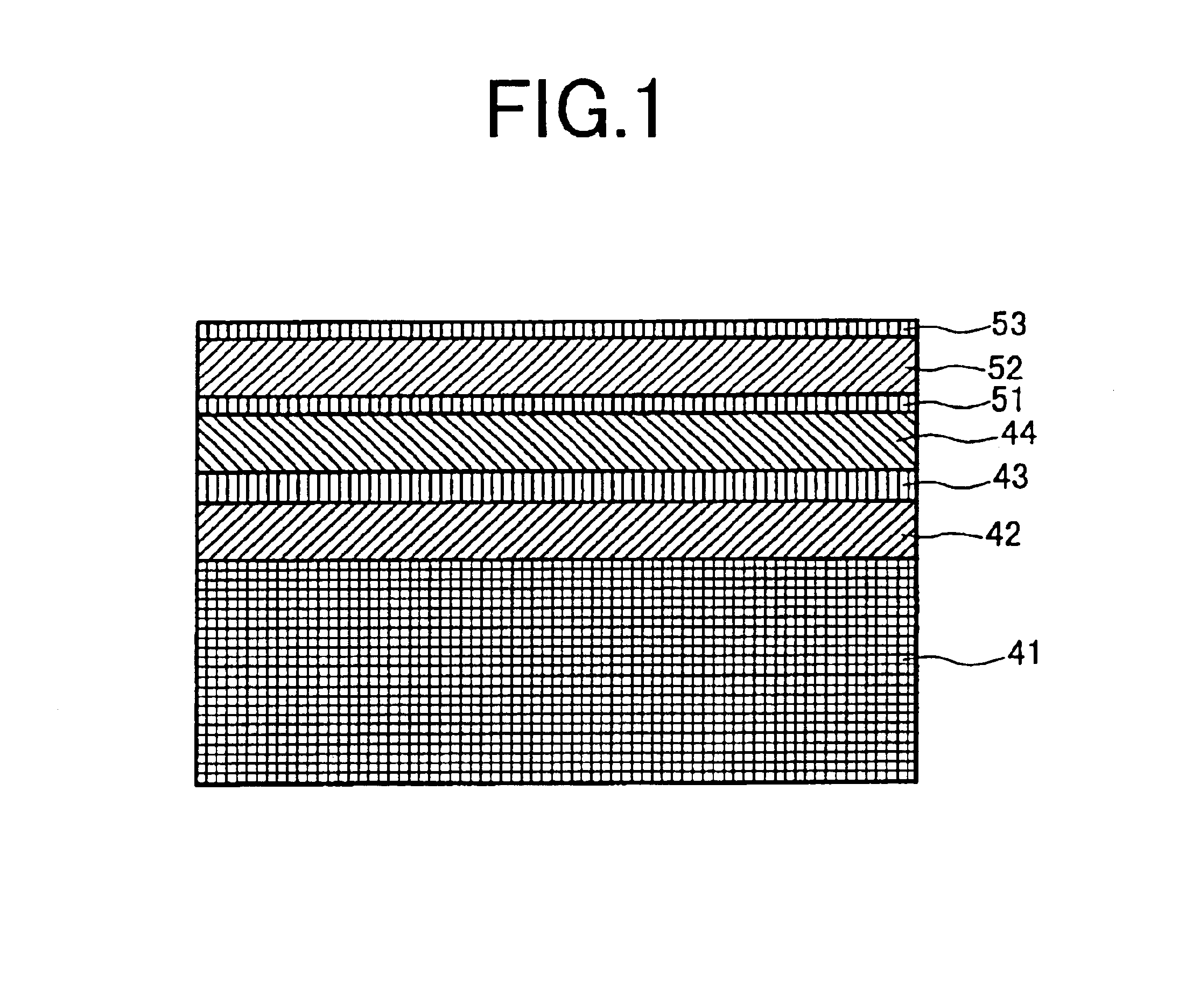
[0028]Using a glass substrate having a diameter of 2.5 inches, a magnetic recording medium having a cross-sectional structure as illustrated in FIG. 1 was produced by a DC magnetron sputtering method. A magnetic under layer including a first layer 42, a second layer 43 and a third layer 44 was formed on a substrate 41. A perpendicular magnetic layer (CoCrPt) 52 having a thickness of 25 nm and a protective layer 53 having a thickness of 5 nm were formed in this order on the magnetic under layer via an intermediate under layer (TiCr) 51 having a thickness of 5 nm. Two different media were produced, one in which the first layer 42 and the third layer 44 were both made of Co with a thickness of 30 nm, and the other in which the first layer 42 and the third layer 44 were both made of CoFe with a thickness of 30 nm. In both media, the second layer 43 was made of Ru.

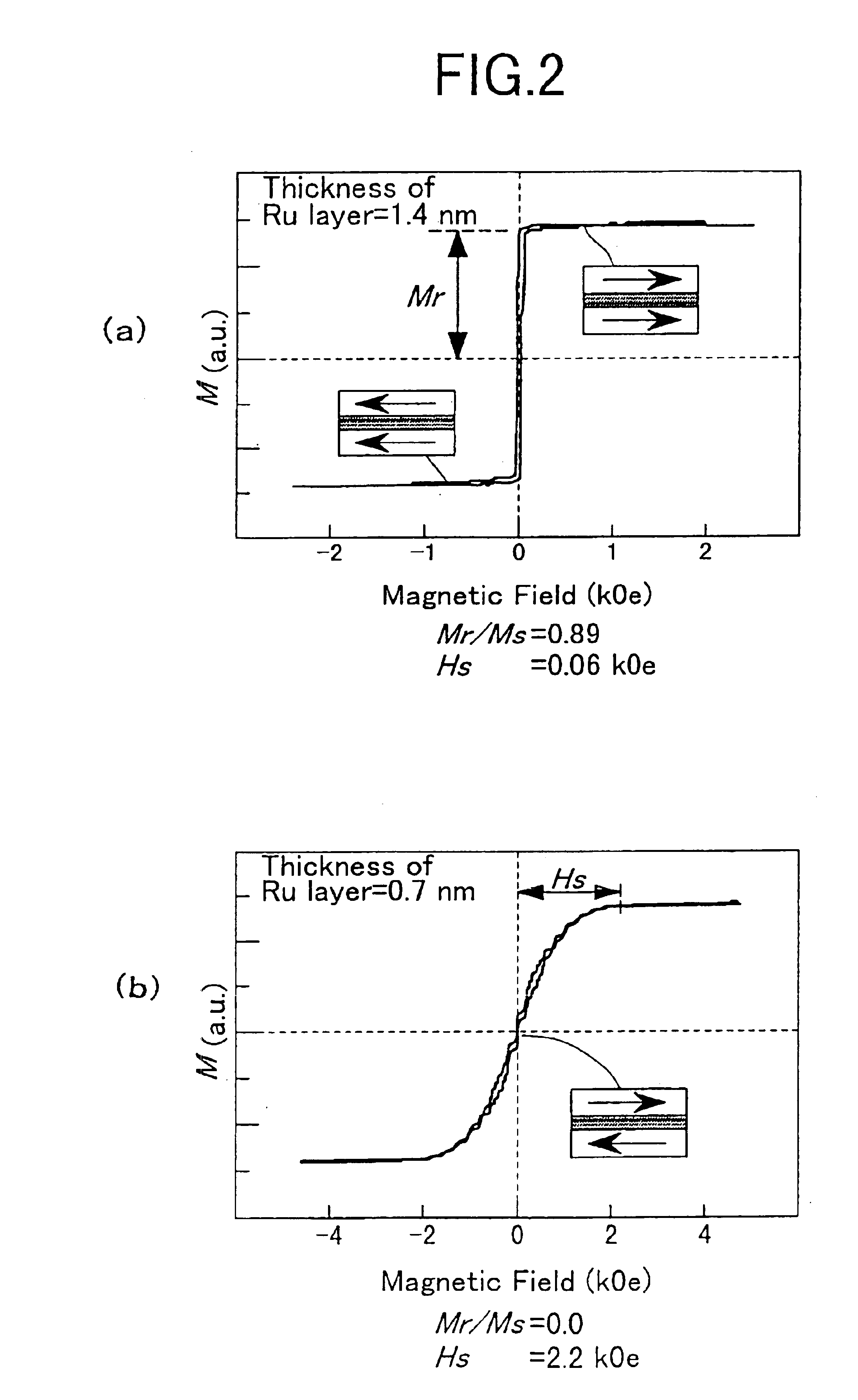
[0029]FIG. 2A to FIG. 3B illustrate the results of measurements performed for the Ru layer thickness dependency of the magnet...

example 2

[0041]A magnetic storage apparatus as illustrated in FIG. 9 was produced by using a disk (FIG. 7) obtained by depositing the perpendicular magnetic recording medium of Example 1 on both sides of a substrate, and a read / recording head (FIG. 8) having a high efficiency read back element based on the giant magnetoresistive (GMR) effect.

[0042]The magnetic storage apparatus is of a well-known structure and includes a magnetic recording medium (disk) 91, a driving section 92 for rotating the magnetic recording medium 91, a magnetic head 93 having a magnetic write section and a read back section, a magnetic head driving section 94 for relatively moving the magnetic head 93 with respect to the magnetic recording medium 91, a signal processing section 95 for processing signals read / written by the magnetic head 93, and a load / unload mechanism 96.

[0043]FIG. 7 is a schematic cross-sectional view illustrating the disk. The disk includes a substrate 27 made of NiAl, a magnetic layer 26 (26′) made...

example 3

[0045]Another evaluation was made while using a different perpendicular magnetic recording medium with the magnetic storage apparatus schematically illustrated in FIG. 9. FIG. 10 is a schematic cross-sectional view illustrating the perpendicular magnetic recording medium. The perpendicular magnetic recording medium includes a substrate 101 made of glass, a Co layer 102 having a thickness of 40 nm, an Ru layer 103 having a thickness of 0.7 nm, a Co layer 104 having a thickness of 40 nm, a Co-based amorphous ferromagnetic layer 105 having a thickness of 20 nm, a non-magnetic intermediate layer 106 having a thickness of 2 nm, a perpendicular magnetic layer 107 made of CoCrPtB and having a thickness of 30 nm, and a protective layer 108 made of carbon and having a thickness of 3 nm. The layers 102 to 108 are deposited in this order on the substrate 101.

[0046]In the perpendicular magnetic recording medium, the portion from the Co layer 102 to the Co-based amorphous ferromagnetic layer 105...


PUM


Abstract

An improved perpendicular magnetic recording medium and an improved magnetic storage apparatus are provided, which are suitable for high speed and high density magnetic recording. A magnetic under layer of a two-layered perpendicular magnetic recording medium includes three layers: a ferromagnetic layer; a non-magnetic layer; and a ferromagnetic layer, wherein the ferromagnetic layers are antiferromagnetically coupled with each other, thereby preventing a magnetic flux from a magnetic wall in a magnetic under layer from entering a read back head.

Description

BACKGROUND OF THE INVENTION[0001]1. Field of the Invention[0002]The present invention relates to a perpendicular magnetic recording medium suitable for high density magnetic recording, and a magnetic storage apparatus using the same.[0003]2. Description of the Related Art[0004]Along with the rapid propagation of personal computers, work stations, and the like, there has been a growing demand for increasing the capacity of a magnetic disk apparatus, which is the core of a non-volatile file system. In order to increase the capacity of a magnetic disk apparatus, it is necessary to increase the recording bit density, i.e., the plane recording density. A recording system employed for currently-used magnetic disk apparatuses is called “in-plane recording system”. In this system, a ferromagnetic layer having a large coercivity in a direction parallel to the disk substrate plane is used as a recording medium, and information is recorded by magnetizing the recording medium in a direction in ...

Claims


Application Information

Patent Timeline
IPC IPC(8): G11B5/66G11B5/667G11B5/64G11B5/65G11B5/738
CPCG11B5/66G11B5/676
Inventor KAWATO, YOSHIAKIFUTAMOTO, MASAAKINAKAMOTO, KAZUHIRO
Owner WESTERN DIGITAL TECH INC
Why Eureka
Try Eureka