
Optical discriminator for transmitting and receiving in both optical fiber and free space applications

Inactive Publication Date: 2005-08-02
MOOG INC
View PDF13 Cites 17 Cited by
  • Summary
  • Abstract
  • Description
  • Claims
  • Application Information

AI Technical Summary

Benefits of technology

[0011]The present invention is directed to the object of providing an improved bi-directional optical transmission and reception arrangement which can be constructed more compactly in comparison to present-day arrangements. The arrangement of the present invention is particularly useful for communications networks and / or rangefinding devices.
[0012]This object is achieved by an improvement in a bi-directional optical transmission and reception arrangement which is composed of an optical transmitter having an exit pupil for the emission of an optical radiation having a first wavelength, an optical discriminator having an optical detector for the reception of optical radiation having a second wavelength, an optical delivery means for delivering the radiation having the first wavelength emitting from the transmitter to a predetermined spatial point at a distance from the transmitter and from the discriminator and for delivering the radiation having the second wavelength emitting from another co-axial spatial point to the discriminator, comprising a wavelength-selective interference filter that is non-transmissive or reflective for the radiation of the first wavelength and is only transmissive for the radiation of the second wavelength, whereby the optical filter is disposed on or within the optical detector. By virtue of this arrangement, the present invention provides a uniquely compact and efficient system that is more economical and easier to manufacture.

Problems solved by technology

The conventional bi-directional transmission and reception systems suffer from numerous drawbacks related to the size and separate packaging of the individual devices, the cost of manufacture, as well as the difficulty associated with alignment of the system.

Method used


Image

  • Optical discriminator for transmitting and receiving in both optical fiber and free space applications
  • Optical discriminator for transmitting and receiving in both optical fiber and free space applications
  • Optical discriminator for transmitting and receiving in both optical fiber and free space applications

Examples


Embodiment Construction

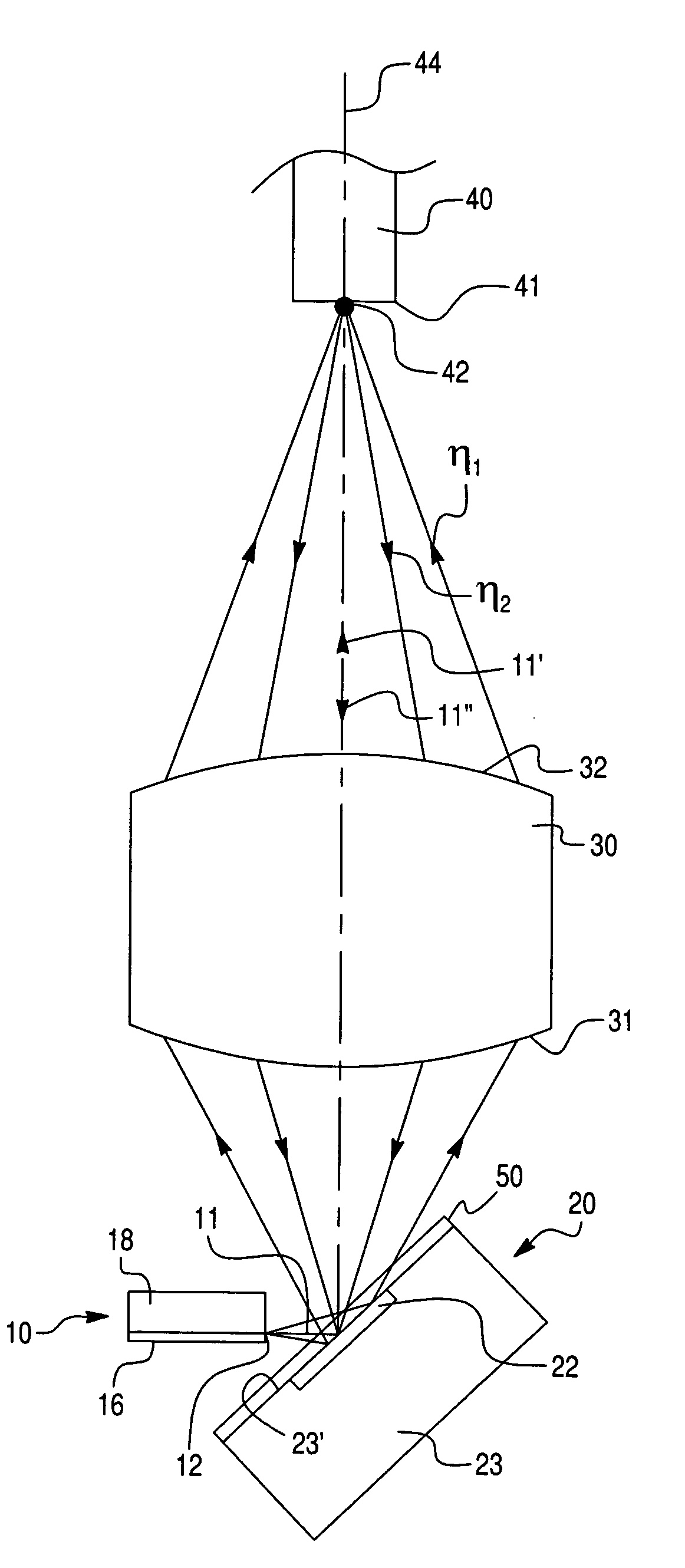
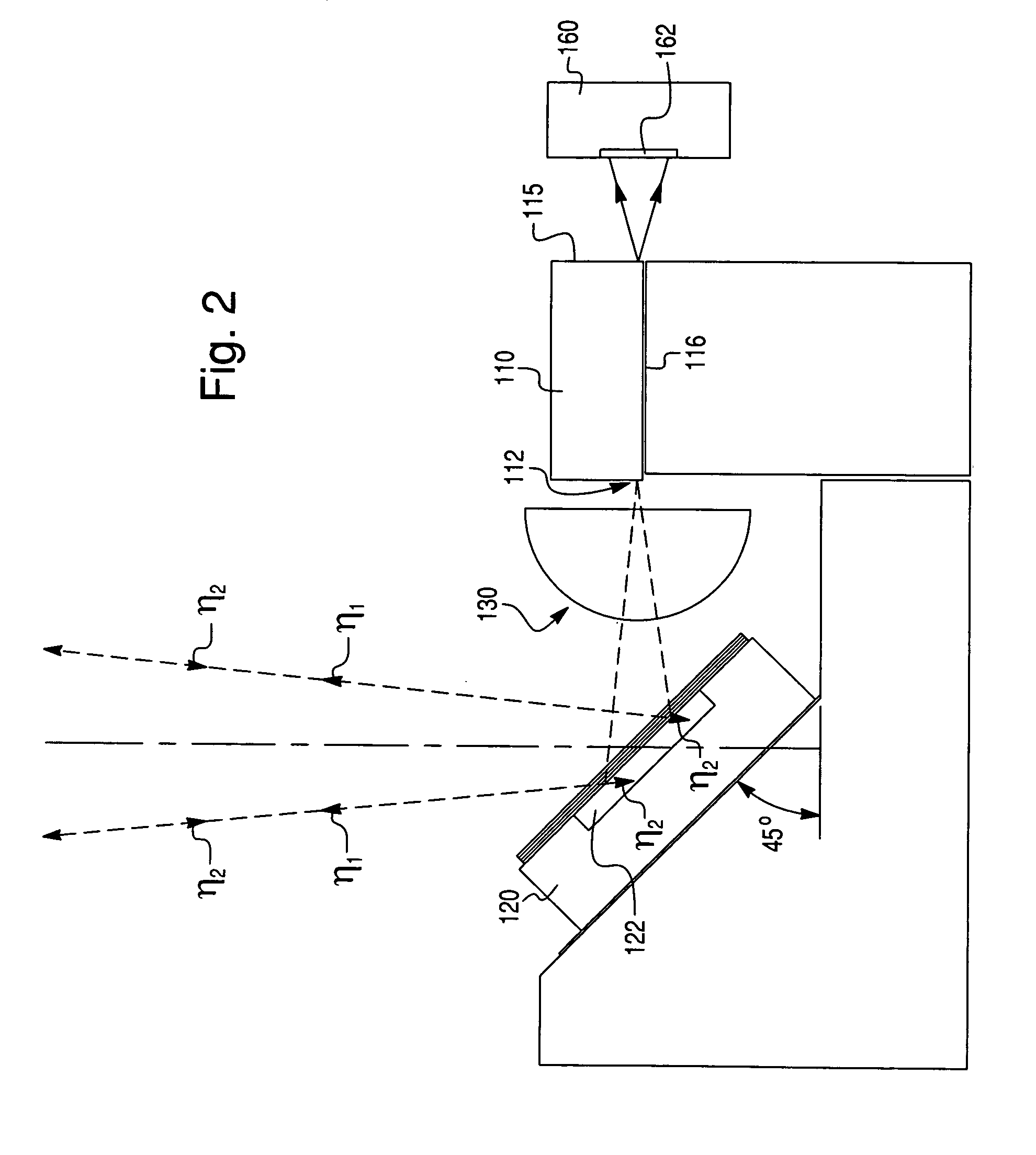
[0021]The principles of the present invention are particularly useful when incorporated in a bi-directional optical transmission and reception arrangement illustrated in FIG. 1. The arrangement of FIG. 1, as well as the arrangements of FIGS. 2–4, each comprise an optical transmitter (e.g., a laser diode source of the edge or surface emitting type), generally indicated at 10, having a transmission exit pupil 12 for emitting an optical radiation having the first wavelength λ1. The optical transmitter 10 is aimed at an optical discriminator (e.g., a PIN photodiode having a dichroic thin film coating), generally indicated at 20, having an absorbing region 22 acting as a receiver window for the reception of an optical radiation of the second wavelength λ2, whereby the optical discriminator 20 is preferably disposed at an angle of 45° with respect to the axis of the optical transmitter 10.

[0022]As will become apparent from this description, an important feature of the instant invention is...


PUM


Abstract

A bi-directional communication assembly is provided with commonly available optoelectronic components in a compact package. Diplex functionality is achieved by orienting the receiving detector at an angle with respect to the transmitting beam. An interference coating inside the detector, on the detector surface, or on a surface in intimate contact with the detector, reflects the transmitted beam while simultaneously allowing the receiving beam to pass through the coating to the light absorbing region. The combined function of the receiving detector, providing advantages of a common beam path and close proximity of the components, enable a compact package that can be placed within the space usually occupied by the transmitter light source alone.

Description

CROSS-REFERENCES TO RELATED APPLICATIONS[0001]There are no applications that are related to the present application.STATEMENT AS TO RIGHTS TO INVENTIONS MADE UNDER FEDERALLY-SPONSORED RESEARCH AND DEVELOPMENT[0002]There are no rights that require licensing of the present application.BACKGROUND OF THE INVENTION[0003]1. Field of the Invention[0004]Bi-directional optical communications of arbitrary signals, including but not limited to digital communication streams or short pulses (for example), at the same or differing wavelengths, either coupled to optical fibers or propagated in free space, whereby an interference filter is disposed on or in the photodetector.[0005]2. Description of Related Art[0006]Optical wavelength division multiplexing is a known technique for combining a plurality of optical signals having different wavelengths and inserting the wavelengths into a single optical fiber. The multiple wavelength signal is transmitted through the fiber to a receiving end where the ...

Claims


Application Information

Patent Timeline
IPC IPC(8): H04J14/02H04B10/24H04B10/10
CPCH04B10/1125H04B10/40
Inventor HEINEY, ALLAN
Owner MOOG INC
Learn More