
System and Method for Cache Coherency In A Multiprocessor System

Active Publication Date: 2009-06-25
IBM CORP
View PDF4 Cites 7 Cited by
  • Summary
  • Abstract
  • Description
  • Claims
  • Application Information

AI Technical Summary

Benefits of technology

[0013]It is, therefore, one aspect of the present invention to provide for an improved cache coherency meth

Problems solved by technology

However, this approach suffers from the obvious drawback that casting out all lines all the way to memory is inefficient and hinders performance.
Further, this method does not enable one core to share another core's cache when that cache is underutilized.
Additionally, this approach does not allow a cache to be employed when its core is powered down in sleep mode or has been deactivated because of a core manufacturing defect.
This approach, however, adds an extra cache and supporting hardware, which consumes a greater area and power than the L2 cache by itself.
Additionally, typical victim caches ordinarily allot space for only one or two lines per congruence class, compared to the six to eight lines in a standard cache, which therefore provides only a limited solution.
The Former approach suffers from the disadvantage that it lacks a mechanism to track whether a cache line has been previously moved.
As such, evicted lines in the Former system can circulate from cache to cache indefinitely, which can cause unnecessary bandwidth costs and hamper system performance.
The Garg approach therefore also suffers from the disadvantages of a single shared cache.
Specifically, Garg line replacement methods must search multiple L2 caches, which increases search time.
Additionally, because no Garg cache contains all the associativity for a particular congruence class, a cache replacement placed in one L2 cache will still miss in a local L2 not containing the cache line, which would ordinarily hit in a conventional system.

Method used


Image

  • System and Method for Cache Coherency In A Multiprocessor System
  • System and Method for Cache Coherency In A Multiprocessor System
  • System and Method for Cache Coherency In A Multiprocessor System

Examples


Embodiment Construction

[0023]The particular values and configurations discussed in these non-limiting examples can be varied and are cited merely to illustrate at least one embodiment and are not intended to limit the scope of the invention.

[0024]In the following discussion, numerous specific details are set forth to provide a thorough understanding of the present invention. Those skilled in the art will appreciate that the present invention may be practiced without such specific details. In other instances, well-known elements have been illustrated in schematic or block diagram form in order not to obscure the present invention in unnecessary detail. Additionally, for the most part, details concerning network communications, electromagnetic signaling techniques, user interface or input / output techniques, and the like, have been omitted inasmuch as such details are not considered necessary to obtain a complete understanding of the present invention, and are considered to be within the understanding of per...


PUM


Abstract

A method for maintaining cache coherency operates in a data processing system with a system memory and a plurality of processing units (PUs), each PU having a cache, and each PU coupled to at least another one of the plurality of PUs. A first PU receives a first data block for storage in a first cache of the first PU. The first PU stores the first data block in the first cache. The first PU assigns a first coherency state and a first tag to the first data block, wherein the first coherency state is one of a plurality of coherency states that indicate whether the first PU has accessed the first data block. The plurality of coherency states further indicate whether, in the event the first PU has not accessed the first data block, the first PU received the first data block from a neighboring PU.

Description

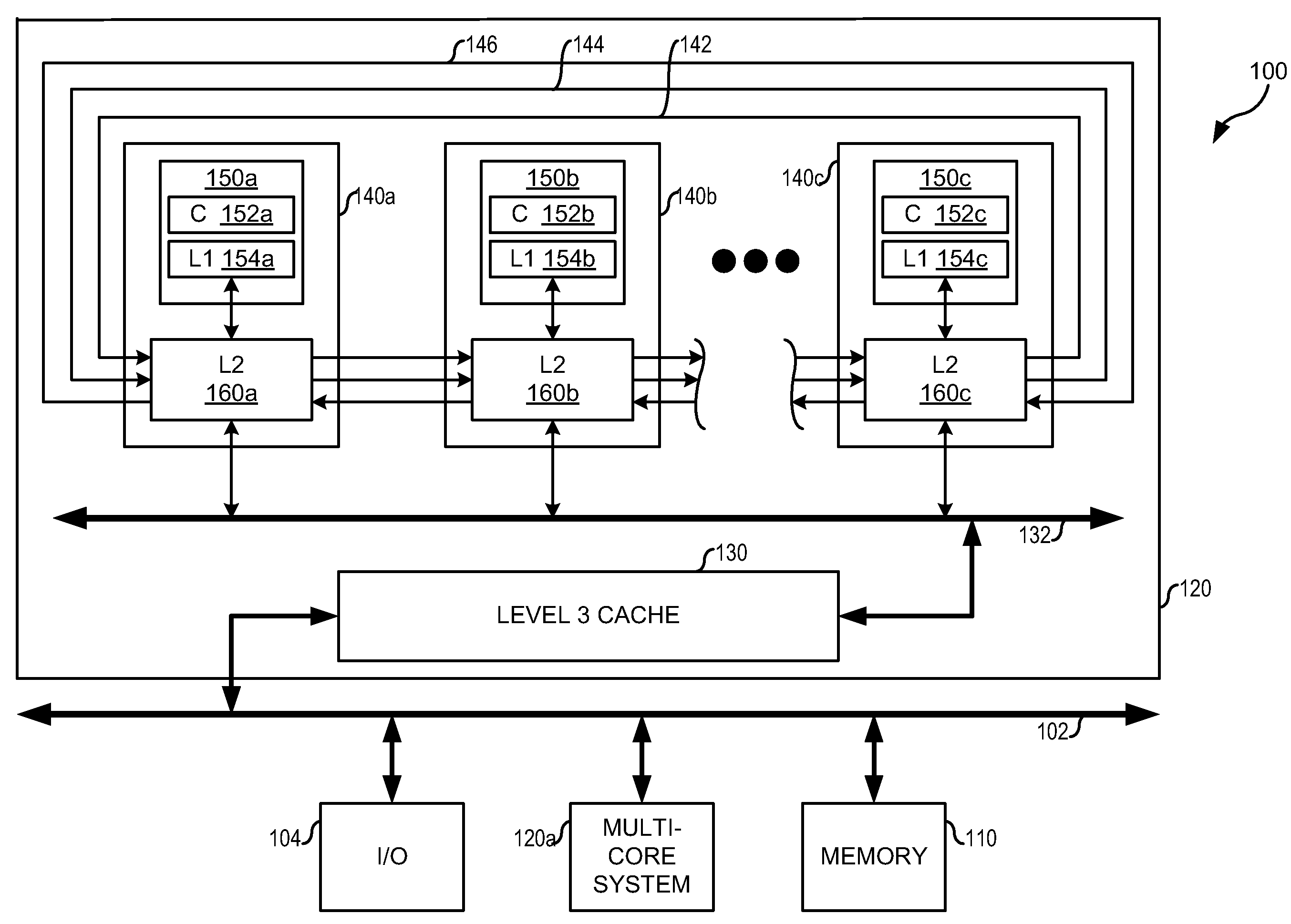
TECHNICAL FIELD[0001]The present invention relates generally to the field of computer networking and parallel processing and, more particularly, to a system and method for improved cache coherency in a multiprocessor system.BACKGROUND OF THE INVENTION[0002]Modern electronic devices often include multiple processors, each sometimes referred to as a processing unit (PU), that each include core logic (a “core”), a level one (L1) cache, and a level 2 (L2) cache. Typically, each core can access only its own dedicated L2 cache, and cannot normally access the L2 cache of a nearby PU.[0003]One skilled in the art will understand that there are many scenarios in which a core does not use its dedicated L2 cache to the maximum extent possible. For example, this may occur when a core executes code that uses the L2 cache only slightly or code from locked cache ways, when a core is powered down or in sleep mode, or when a core has been disabled, as, for example, in response to a detected manufactu...

Claims


Application Information

Patent Timeline
IPC IPC(8): G06F12/00
CPCG06F12/0811G06F12/084G06F12/0831G06F12/0813
Inventor NICHOLAS, RICHARDCOX, JASON ALANDORSEY, ROBERT JOHNLE, HIEN MINHROBINSON, ERIC FRANCISTRUONG, THUONG QUANG
Owner IBM CORP
Learn More