
Straight-through rotary valve structure

Inactive Publication Date: 2010-11-04
HSIAO KUO MING
View PDF14 Cites 8 Cited by
  • Summary
  • Abstract
  • Description
  • Claims
  • Application Information

AI Technical Summary

Benefits of technology

[0010]It is therefore a primary object of the present invention to provide an improved straight-through rotary valve structure. At least one valve block bearing is disposed between the case and the rotary valve block of the rotary valve structure to reduce rotational friction therebetween. Therefore, the rotary valve structure has lower frictional wear and is easier to operate.
[0011]It is a further object of the present invention to provide the above straight-through rotary valve structure, in which the bearing is durable and easy to maintain. Therefore, it is unnecessary to apply any grease between the rotary valve block and the case so that the maintenance process is simplified to facilitate the use.

Problems solved by technology

1. The conic face of the rotary valve block 20 contacts with the inner conic face of the receiving space 11 of the case 10 with a very large frictional force therebetween. In case of poor maintenance or improper operation, it will be hard to smoothly operate the rotary valve block 20.
2. There is a very large frictional force between the rotary valve block 20 and the case 10 so that it is necessary to apply a grease between the rotary valve block 20 and the case 10 to reduce the frictional force therebetween. This complicates the maintenance process and causes inconvenience in use of the trombone.
3. When playing the trombone, the saliva of the player is easy to infiltrate between the rotary valve block 20 and the case 10. The saliva must be cleared up in time. Otherwise, the rotary valve block 20 and the case 10 are very likely to rust and damage.

Method used


Image

  • Straight-through rotary valve structure
  • Straight-through rotary valve structure
  • Straight-through rotary valve structure

Examples


Embodiment Construction

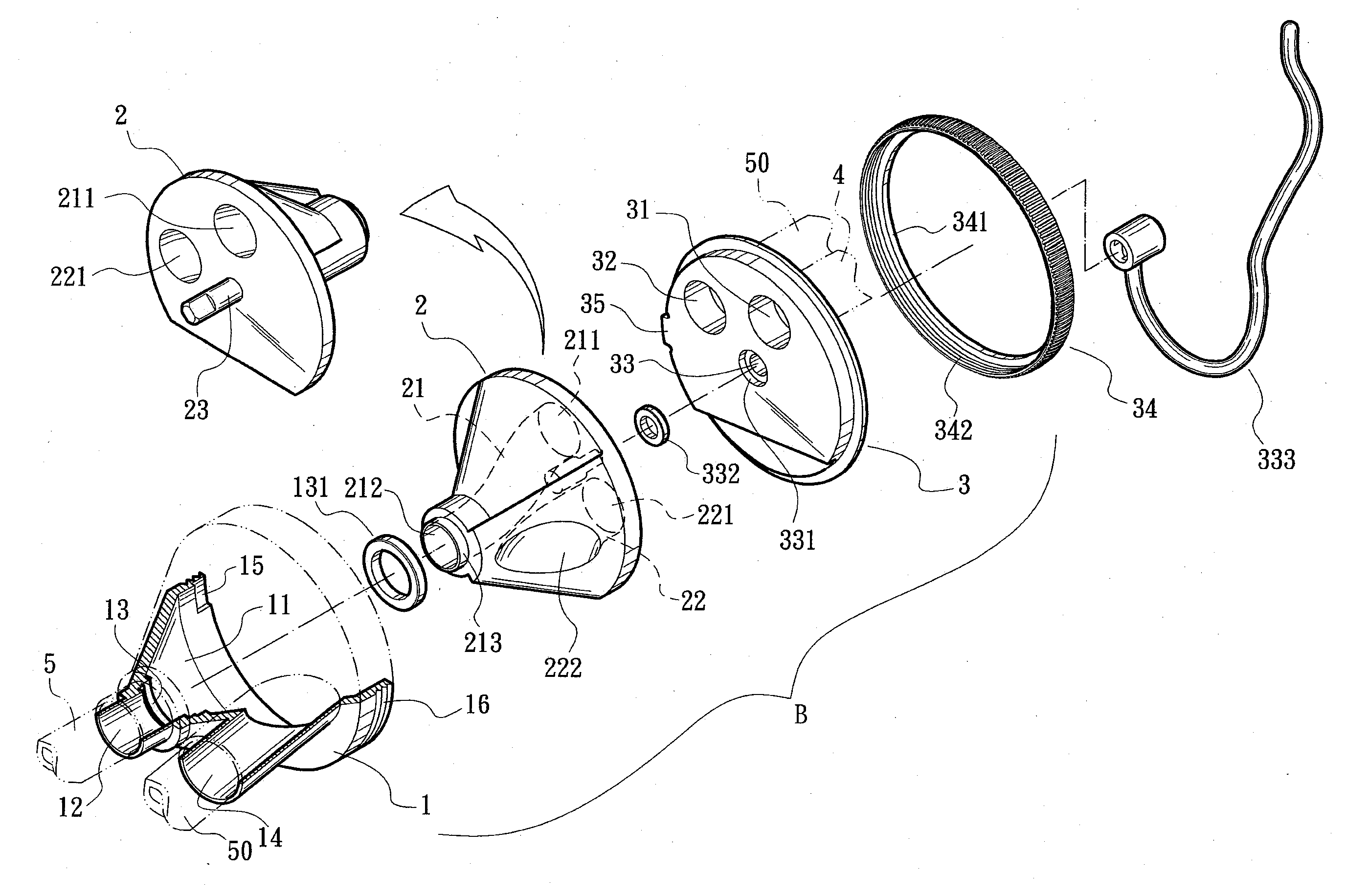
[0021]Please refer to FIGS. 5 and 6. The straight-through rotary valve structure B of the present invention includes a case 1, a rotary valve block 2 and an outer cover 3. The case 1 is formed with an internal conic receiving space 11 with an opening. A tubular first extension section 12 is disposed at a tip of the receiving space 11 in communication with an exterior of the case 1 for connecting with a main tuning tube 5 of a trombone. A bearing seat 13 is disposed on an inner side of the first extension section 12 for receiving a valve block bearing 131. In addition, a second extension section 14 is disposed on the case 1 beside the first extension section 12 for externally connecting with one end of a tuning loop 50. A locating recess 15 is formed on an inner circumference of the opening of the receiving space 11. In addition, an outer thread 16 is formed on an outer circumference of the opening. The rotary valve block 2 is a conic body. A pivot shaft 23 with a cut face is dispose...


PUM


Abstract

A straight-through rotary valve structure includes: a case having an internal conic receiving space with an opening, a first extension section being disposed at a tip of the receiving space, a second extension section being disposed beside the first extension section; a conic rotary valve block having a pivot shaft and formed with a first hole and a second hole, the first hole communicating with a third hole formed at a tip of the rotary valve block in communication with the first extension section, the second hole communicating with a fourth hole formed on a conic face of the rotary valve block; and an outer cover blocking the opening of the case. The outer cover is formed with a central shaft hole through which the pivot shaft passes. The outer cover is further formed with a first perforation and a second perforation corresponding to the first and second holes respectively.

Description

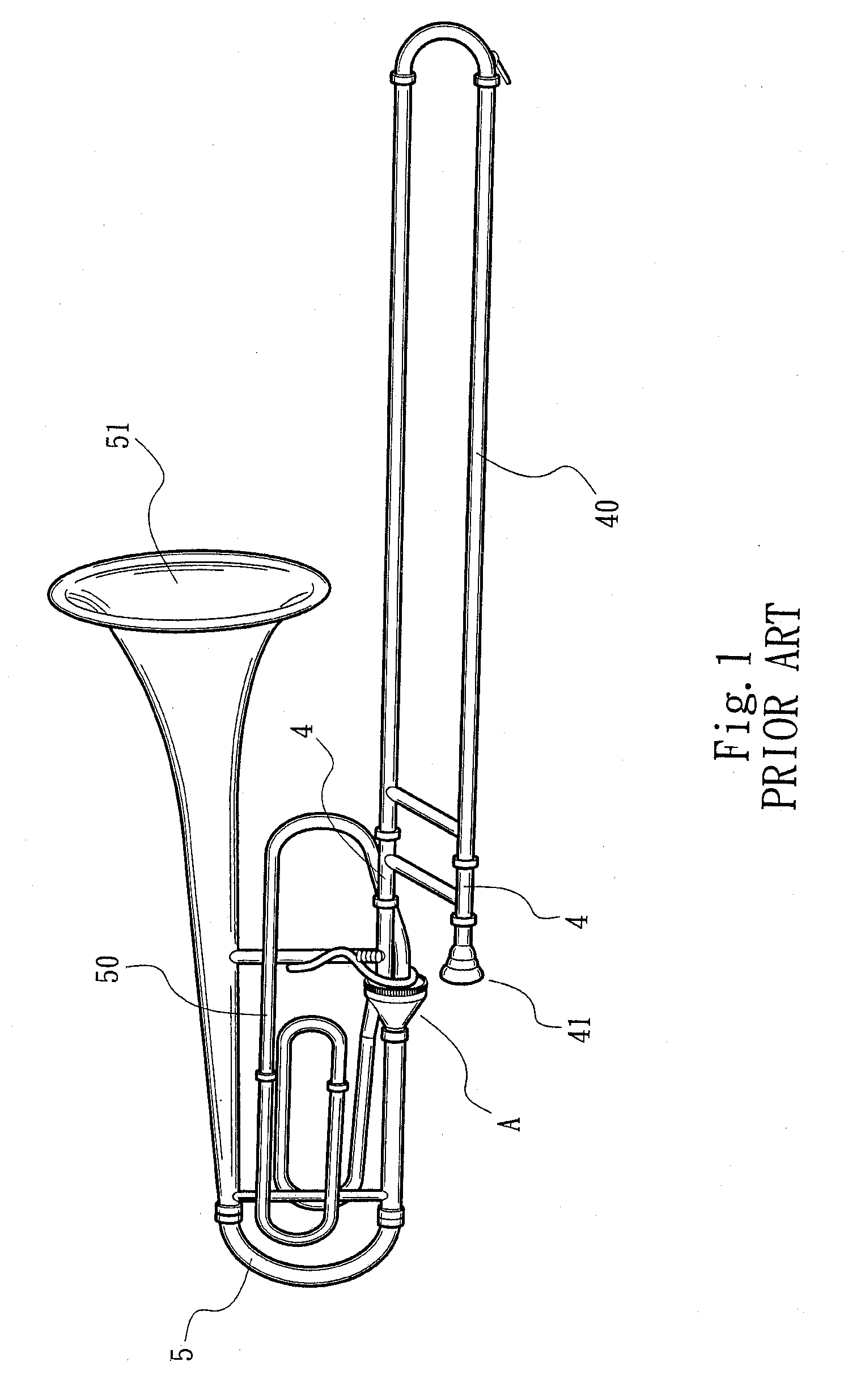
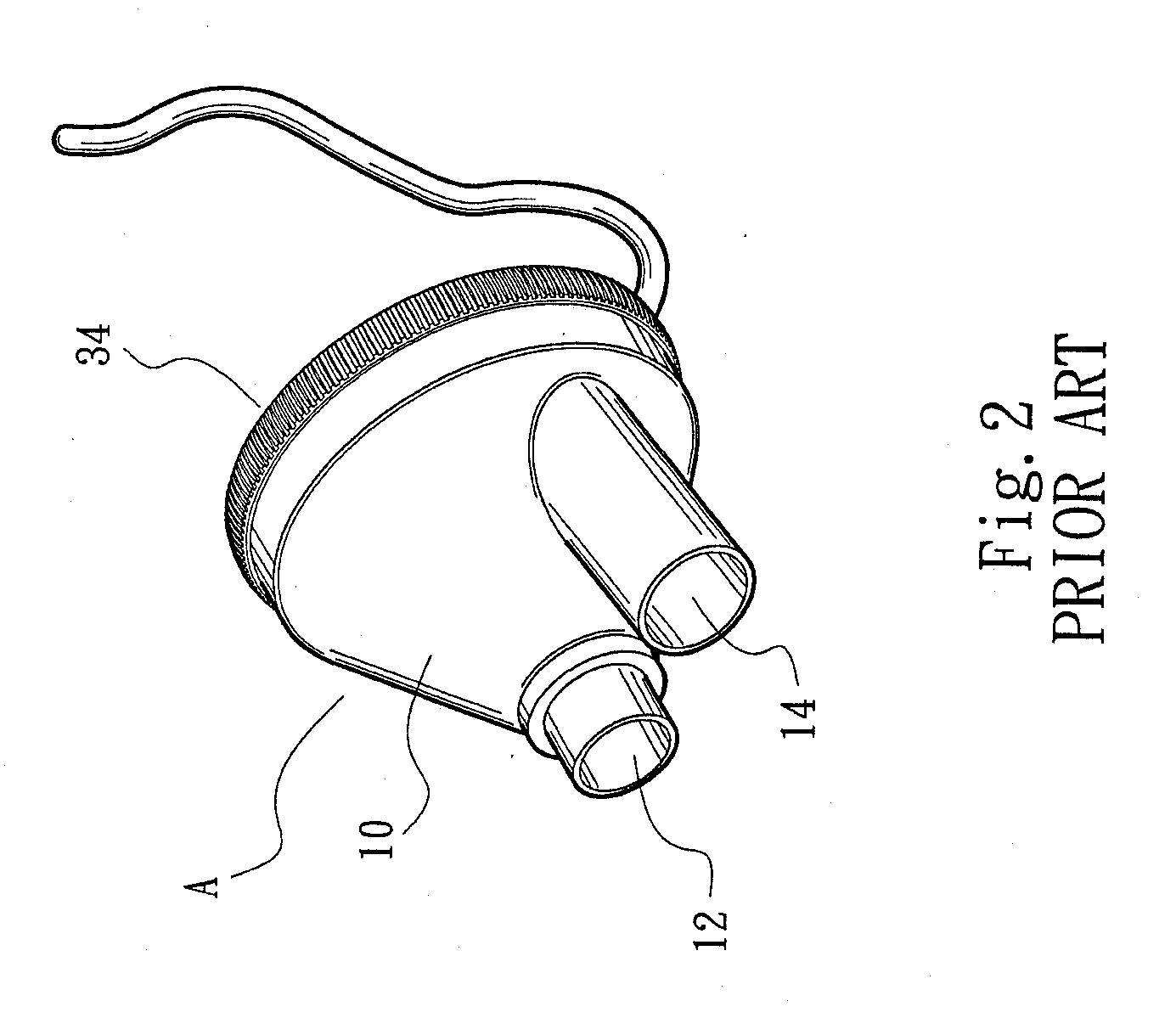
BACKGROUND OF THE INVENTION[0001]1. Field of the Invention[0002]The present invention relates generally to an improved straight-through rotary valve structure, and more particularly to a rotary valve structure of a trombone, which has lower frictional wear and is easy to maintain and operate.[0003]2. Description of the Related Art[0004]The trombone is a brass instrument. Please refer to FIG. 1, which shows the structure of a conventional trombone. The trombone mainly has a telescopic slide 40, two inner tubes 4 arranged in parallel to each other, a rotary valve main body A, a main tuning tube 5 and a tuning loop 50. The telescopic slide 40 is a crooked tube body telescopically fitted with first ends of the inner tubes 4. A mouthpiece 41 is connected to a second end of one of the inner tubes 4. A second end of the other of the inner tubes 4 is connected to an inlet of the rotary valve main body A. Two ends of the tuning loop 50 are connected to the rotary valve main body A. The main ...

Claims


Application Information

Patent Timeline
IPC IPC(8): G10D7/10F16K5/02
CPCF16K5/02F16K5/0207G10D9/04G10D7/10F16K5/16
Inventor HSIAO, KUO-MING
Owner HSIAO KUO MING
Learn More