
Methods, systems and computer program products for color matching

Inactive Publication Date: 2005-08-02
DIGITAL COLOR MEASUREMENT
View PDF10 Cites 28 Cited by
  • Summary
  • Abstract
  • Description
  • Claims
  • Application Information

AI Technical Summary

Benefits of technology

[0027](vi) means for generating a third digital image corresponding to the second digital image, but replacing the colour attributes selected from the database for each pixel with mutually distinguishable false-colour attributes so as to form a contour image clearly distinguishing respective sets of pixels sharing the same predetermined colour attributes.
[0037]Preferably, the digital image of the article is captured directly with a digital camera, the camera advantageously being provided with cross-polarised filtration. Typically this is achieved by a pair of cross-polarised filters, preferably the filters are grey so as provide a minimal colour temperature shift whilst simultaneously providing good transmission. The effect of cross-polarised photography is to control reflections, lustre and to cut out glare.
[0038]Preferably, the camera is pre-set and / or pre-programmed to a specified focal length. For example, the focal length may be 25±2 cm. It is desirable to try to reduce any deviations in focal length so as to minimise errors that may occur by virtue of variations in, or non-uniform, illumination.
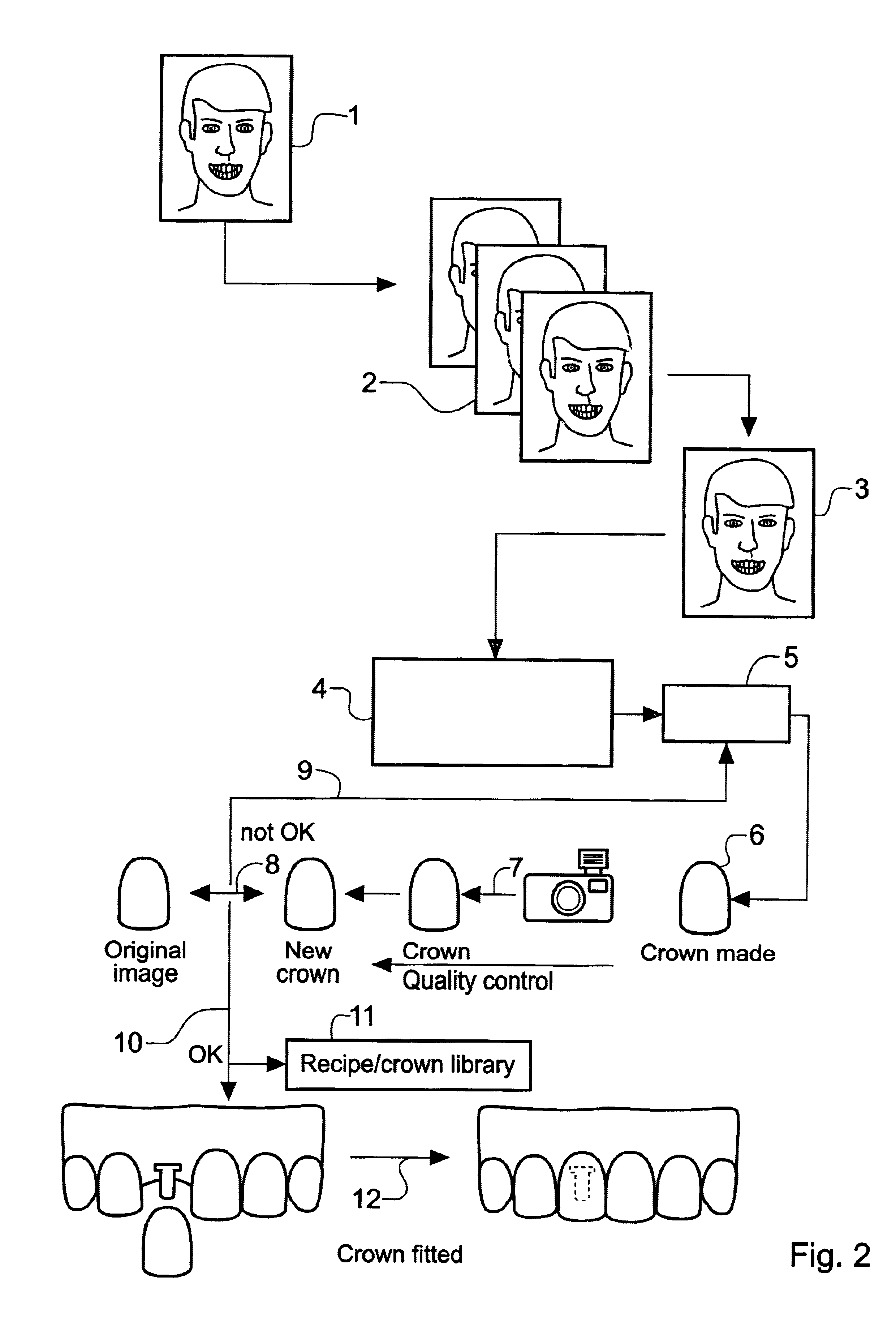
[0040]Preferably, the reference colour is grey and more preferably still the grey is cool grey C pantone number 8. The reference indicator may take the form of a substantially U or L shaped block. The reference indicator may also be labelled so that the image of the object can easily be identified or cross referenced.
[0044]The database of predetermined colour attributes will generally contain fewer discrete attributes than are present within the true-colour digital image. In a particularly preferred application of the present invention, which is to generate dental prostheses from ceramics or the like of known colours so as closely to match a patient's natural tooth colours, the database will contain the colour attributes of a range of available ceramics materials or the like. The database may contain several subsets of ceramics colours corresponding to the ranges of colours offered by different ceramics manufacturers. At present, most manufacturers of ceramics for use in dental prostheses offer one or more discrete ranges of about sixteen subtly different shades. Hitherto, dental prostheses have been made using a single shade or colour of ceramic which has been subjectively judged to be the closest match to a patient's existing tooth or teeth. However, by way of the present invention, it is possible to determine shade variations within a single tooth and to replicate these shade variations in a prosthesis by selecting the closest match from the predetermined range of ceramics colours for individual areas of the tooth, and then to construct a prosthesis by painting or otherwise applying different shades of ceramics to a base prosthesis so as broadly to match the colour variations in the natural tooth. This is a significant advantage over the prior art.
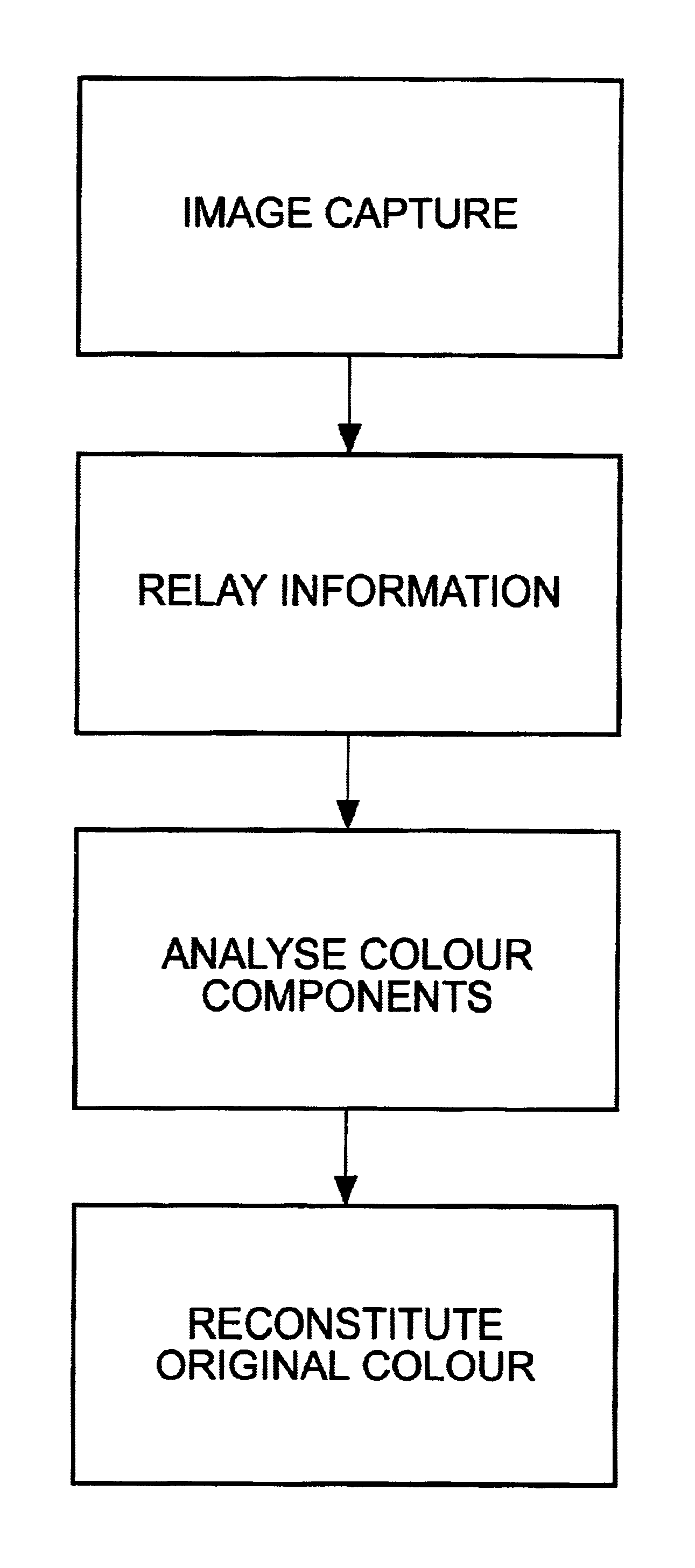
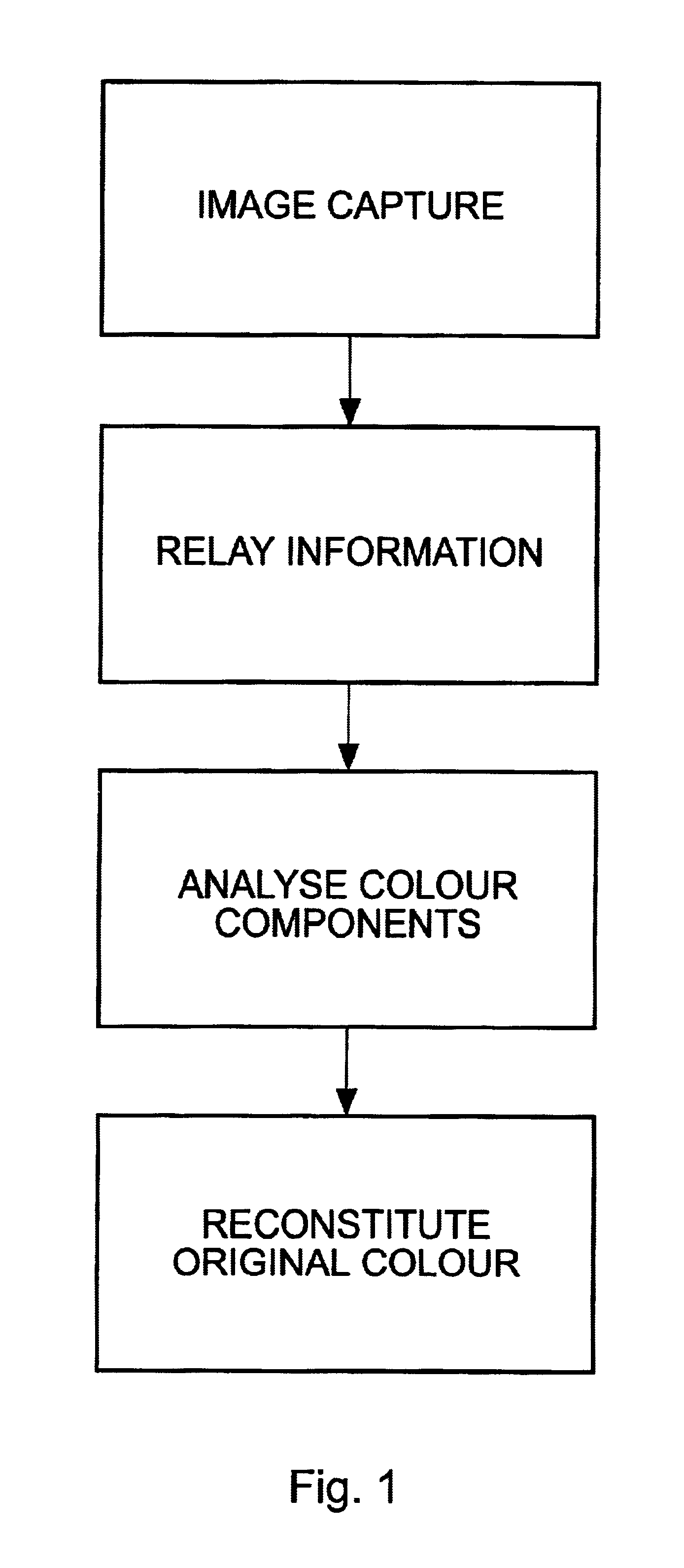
[0049]In use, embodiments of the present invention allow a user to take a photograph of an article, for example a piece of coloured textile and to relay information relating to the photograph to a place remote from where the textile actually is, for example a paint factory. An operator in the paint factory then initiates a software program to analyse the colour values from which a recipe can be generated so that a replica of the colour of the textile can be reconstituted from various ratios of different dyes.

Problems solved by technology

This is a purely subjective evaluation and can lead to a colour mismatch since one person's assessment may differ from another's.
Alternatively, a smooth shiny object can reflect light from its surface leading to bright spots similar colour distortions.
However, it is difficult to critically assess highly reflective surfaces such as the enamel of teeth.
This can be problematic because tooth colour is affected not only by ambient light colour / intensity in the surgery i.e. fluorescent or natural light, but also by the surrounding colour of the patient's own clothing or make-up / complexion.
It will be appreciated this process often results in unacceptable levels of colour mismatching so that a second or replacement dental prosthesis needs to be constructed at a substantial cost and inconvenience to the patient, dental professional and dental prosthesis manufacturer.
The problem with this method is that it does not completely eliminate variations in ambient lighting conditions.photographing the patient's mouth with a reference shade guide in the frame.
The problem with this method is that the equipment can be bulky and that the colour in the photograph may be distorted and / or misrepresented through the process of developing and producing the photograph.
In addition, the flash from the camera causes high levels of reflection from the tooth surface.videoing the patient's mouth with a reference shade guide in the frame.
The problem with this method is that the equipment can be bulky and that the colour in the video may not be accurate.manually drawing and painting / colouring an artist's impression of a tooth.
The problem with this is that it can be expensive, time consuming, and it is not independent of ambient lighting conditions.
None of the prior art methods is capable of capturing an exact colour image of a natural tooth.
Natural teeth are translucent on their surface, the transparencies of dentine and enamel are difficult to correct for when representing the colour of a tooth.
All of these factors contribute to the difficulty in accurately capturing a colour image of a tooth.
A problem not addressed by any of the prior art methods is the subjective colour assessment which the dental laboratory technician has to make when given a recipe or image to work to, so as to construct the dental prosthesis.
Some methods have made improvements in the standardisation of assessing the colour of the patient's tooth in the first instance, but problems remain with human errors in constructing and colour matching the prosthesis to a recipe.

Method used


Image

  • Methods, systems and computer program products for color matching
  • Methods, systems and computer program products for color matching
  • Methods, systems and computer program products for color matching

Examples


Embodiment Construction

[0060]With reference to FIG. 1 there is shown a flow diagram of the steps of a method of colour matching / identification of an object using an embodiment of the present invention. The first step of the method is to capture an image of an object which it is desired to colour match and / or colour identify. This is achieved by first illuminating the object with an appropriate light source and taking at least one photograph of it with a digital camera fitted with cross-polarised filtration. Optionally a colour reference indicator is included in the captured image (see FIG. 4). The camera can be pre-programmed to a specified focal length and arranged to be a selected distance away from the object in order to reduce variations in illumination conditions. The object could be a piece of textile, wall covering, part of a picture which needs to be restored or requires the original colour recorded for posterity, a car body part or a human face for which a suitable cosmetic / hair dye hue can be ma...


PUM


Abstract

A method and system of image processing on a computer, and a computer program product adapted for image processing, wherein a digital image of an article is imported into a computer, the digital image is color-corrected, an internal palette is generated from a database of predetermined color attributes and applied to the color-corrected digital image so as to generate a second digital image, and wherein a third digital image corresponding to the second digital image is generated, but replacing the predetermined color attributes with vivid color attributes. The present invention is of particular utility in the manufacture of dental prostheses from ceramics materials which substantially match a person's natural tooth colors.

Description

RELATED APPLICATIONS[0001]This application claims priority from the following UK Applications: GB 0019297.1, filed 7 Aug. 2000 GB 002702.5, filed 3 Nov. 2000; GB 0103453.7, filed 13 Feb. 2001; GB 0110197.1, filed 26 Apr. 2001; and GB 0113743.9, filed 6 Jun. 2001. This application also claims priority from U.S. Provisional Application No. 60 / 255,461, filed 13 Dec. 2000, and from U.S. Provisional Application No. 60 / 288,592, filed 3 May 2001. These disclosures are hereby incorporated by reference herein in their entirety.FIELD OF THE INVENTION[0002]The present invention relates to a method and system for image processing, for particular, but not exclusive, use in the colour matching of articles such as dental prostheses, textiles, paints, dyes, car body repairs, picture restoration and in the cosmetics industry. In addition, the present invention may be used in the colour identification of the colours of precious metals, gems and stones and for use in the printing and security industri...

Claims


Application Information

Patent Timeline
IPC IPC(8): G01J3/46G06T7/40
CPCG01J3/46G01J3/463G01J3/508G06T7/408G01J3/0224G06T7/90
Inventor LEEDHAM, DAVIDPRIESTLEY, DEREKGILL, MALCOLMBURKINSHAW, STEPHEN MARTINNATTRESS, BRIAN
Owner DIGITAL COLOR MEASUREMENT
Learn More