
Method and circuit arrangement for improved data transmission

a technology of data transmission and circuit arrangement, applied in the direction of transmission, multiple carrier system, modulated carrier system, etc., can solve the problem of number of signal points, achieve optimal use of signal energy, improve data transmission, and improve the effect of data transmission

Inactive Publication Date: 2005-08-02
DEUTSCHE TELEKOM AG
View PDF11 Cites 0 Cited by
  • Summary
  • Abstract
  • Description
  • Claims
  • Application Information

AI Technical Summary

Benefits of technology

[0006]Therefore, the object of the invention is to provide a method and a circuit arrangement for improved data transmission with efficient use of multi-level modulation methods which permit optimal use of the signal energy of signal constellations and by which frequently employed signal constellations, such as 16-QAM, can be used in simple and optimal manner to transmit lower data rates.
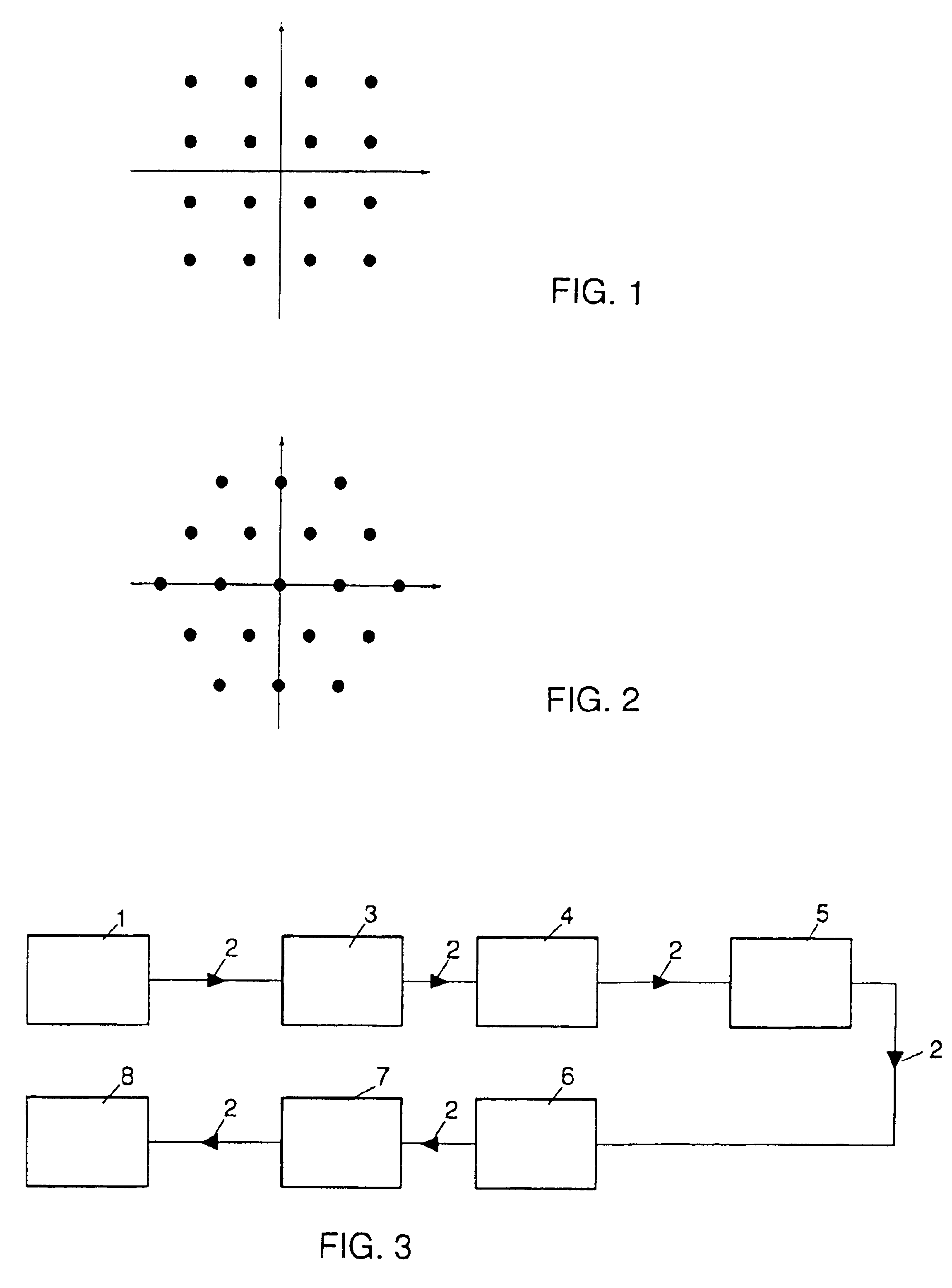
[0009]The method and the circuit arrangement described here permit optimal utilization of the signal energy of signal constellations. This can be of advantage for technical applications in two respects. First of all, signal constellations which are very efficient, but have the disadvantage that the number of signal points is not a power of two, can now be adapted in a simple manner to data formats used in practice, such as a bit sequence. Secondly, frequently employed signal constellations, such as 16-QAM, can be used in simple and optimal manner to transmit lower data rates. Thus, the 16-QAM signal constellation can be used to transmit on average 3 bits per signal point, instead usual 4 bits per signal point. This can be technically useful, for example, in order to switch to 16-QAM with optimized probabilities in existing transmitters and receivers using, for instance, 8-QAM with the points {(+−½, +−½), (+−(1+√ 3) / 2,0), (0,+−(1+√ 3) / 2} as signal constellation (i.e. 3 bits per signal point), accompanied by simultaneous power gain of approximately 1 dB.
[0010]With a method according to the present invention recoding is particularly simple to accomplish when the input data stream is a uniformly distributed sequence, especially a bit sequence. The recoding can then be accomplished using a loss-free decompression method such as the Huffman method. Accordingly, the inverse recoding operation on the receiver end is carried out using the corresponding compression method. A uniformly distributed sequence or bit sequence is obtained, for example, by encryption. This means that the possibly bothersome guarantee or generation of such a sequence can be achieved by the addition of a value-added operation, namely encryption. Since encryption will play an ever greater role in future transmission systems and is already being supplied today along with many systems, the new method is particularly practical. In the recoding of the incoming source bit stream to the signal points which are transmitted through the channel, use is made of a temporary register as buffer that serves to adapt the bit rate, which fluctuates as a function of time due to the transmission through the channel, to the bit rate of the source data. In an implementation of the circuit, this temporary register has a defined fixed length. In practice, this leads to the problem of a “buffer overflow”. To solve this problem, the suggestion here is to select the channel data rate to be greater than the source data rate, it being advantageous to select the channel data rate to be slightly greater than the source data rate. In this manner, it is possible, with relatively little effort and expense, to specify the length of the temporary register or the length of the buffer so that there is only a negligibly small (known) probability of an overflow. When working with a channel data rate which is greater than the source data rate, it may occur that the channel will be ready to transmit information which is not yet available from the source. This effect is utilized here, for example, by transmitting synchronization data instead of the source data. A further solution involves transmitting other header or user data as well, instead of the synchronization data. The greater the channel data rate, the shorter it is possible to select the temporary register.

Problems solved by technology

First of all, signal constellations which are very efficient, but have the disadvantage that the number of signal points is not a power of two, can now be adapted in a simple manner to data formats used in practice, such as a bit sequence.

Method used


Image

  • Method and circuit arrangement for improved data transmission
  • Method and circuit arrangement for improved data transmission
  • Method and circuit arrangement for improved data transmission

Examples


Embodiment Construction

[0019]As stated above, known transmission methods employ orthogonal basis functions to represent the signal to be transmitted. In this case, a message signal s(t) is represented as the sum of orthogonal basis functions. A message signal can be regarded as a point in a K-dimensional space. The entirety of all permissible signal points is referred to as a signal constellation, the “16-QAM” signal constellation shown in FIG. 1, which represents one of the two-dimensional signal constellations, being especially popular.

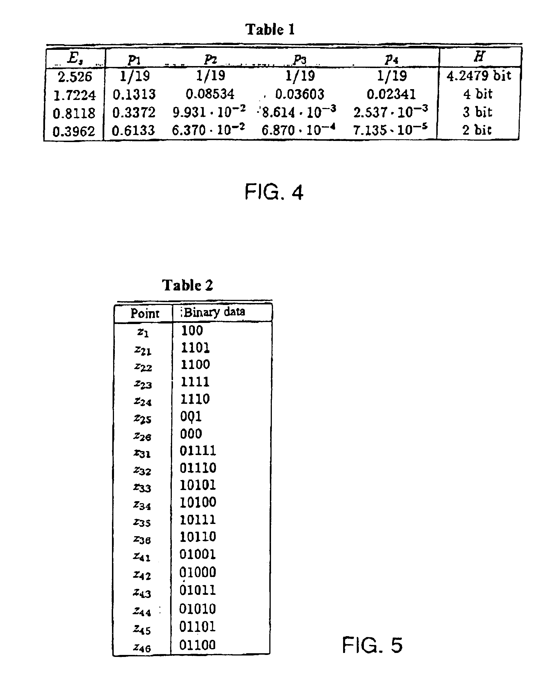
[0020]If a signal constellation has a total of M signal points, Mj of each of which have the signal energy Ej, and if the probability for the occurrence of such a signal point is equal to Pj, then, by setting the probabilities according to the formula given below, one obtains the values which are optimal according to power / information rate for that power. The value L indicates how many different energy levels occur in total.

(Ej−E1) / (EL−E1)

pj=p1(pL / p1) j=1,2, . . . , L an...


PUM


Abstract

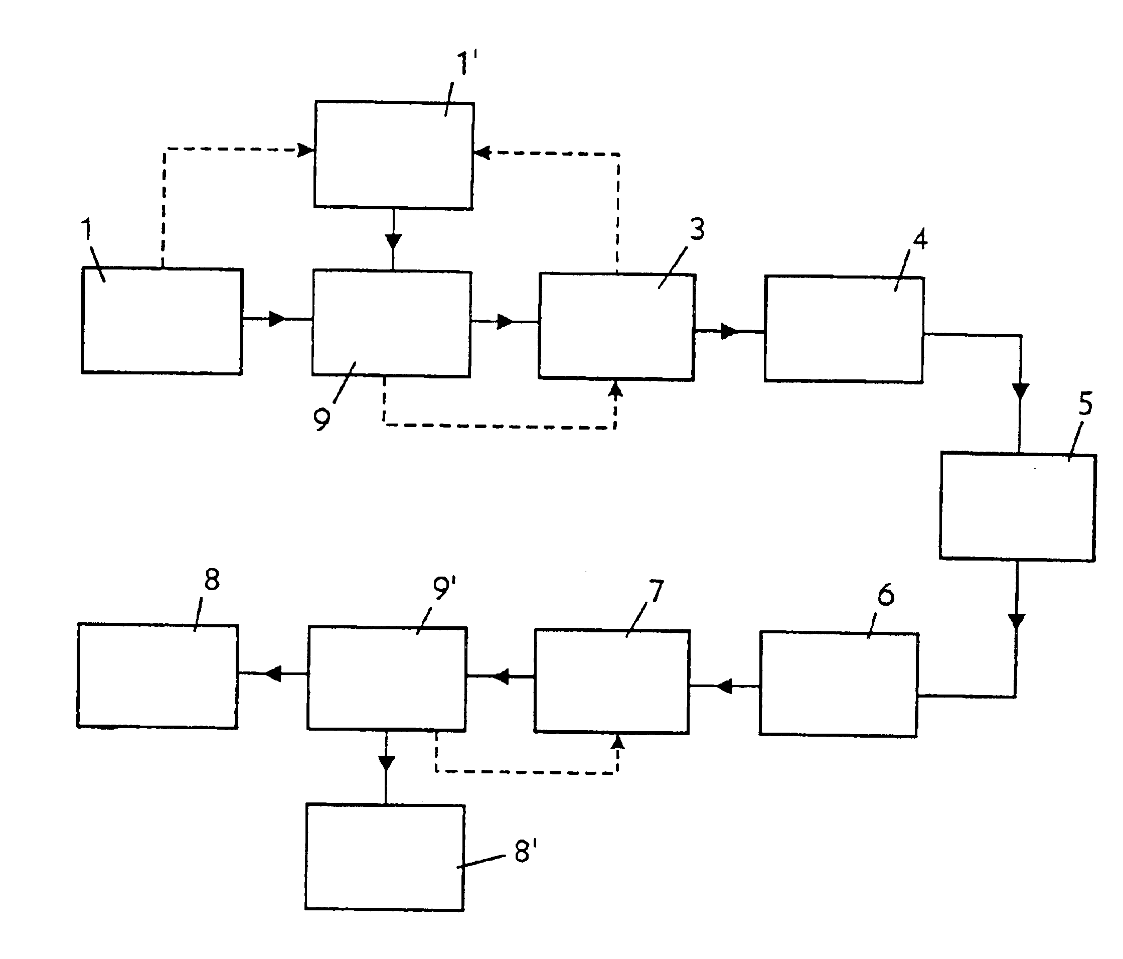
A method and a circuit arrangement for efficient use of multistage modulation methods using orthogonal base functions for the representation of a signal to be transmitted. Signal points of a signal constellation are selected according to a respective predetermined and / or selected probabilities so as to optimize a respective signal energy and / or a respective signal data rate, the selected signal points each having a defined respective energy. A 16-QAM signal constellation can be used, for example, for transmitting at low data rates. In the circuit arrangement, a source (1) which supplies a data stream (2) and is connected to a code converter (3) for converting the data stream. The output of the code converter (3) is connected to a modulator (4) in which the corresponding signal points are selected according to the respective probabilities. The data stream (2) is then transmitted over a channel (5), and a demodulator (6) situated downstream from a code converter (7) carries out the inverse operation.

Description

FIELD OF THE INVENTION[0001]The present invention relates to a method and a circuit arrangement for improved data transmission for efficient use of multi-level modulation processes which employ orthogonal basis functions to represent a signal to be transmitted according to the preambles of claim 1 and claim 9, respectively.RELATED TECHNOLOGY[0002]In telecommunications engineering, transmission methods are known, and also used in practice, which utilize orthogonal basis functions to represent the signal to be transmitted. Such transmission methods are described, for example, in the book of R. E. Blahut, Digital Transmission of Information, Addison-Wesley, Reading, 1990, chapters 2 and 3 which is hereby incorporated by reference herein.[0003]In this case, a message signal s(t) in the baseband is represented as the sum of orthogonal basis functions. In order to integrate the message m=(m0, m1, m2 . . . mk−1)—where the mj are selected from an appropriately chosen alphabet—into the signa...

Claims


Application Information

Patent Timeline
Patent Type & Authority Patents(United States)
IPC IPC(8): H04L27/34H04L27/00
CPCH04L27/3411
Inventor HUBER, KLAUS
Owner DEUTSCHE TELEKOM AG
Learn More