Coaxial connector and cable assembly
- Summary
- Abstract
- Description
- Claims
- Application Information
AI Technical Summary
Benefits of technology
Problems solved by technology
Method used
Image
Examples
Embodiment Construction
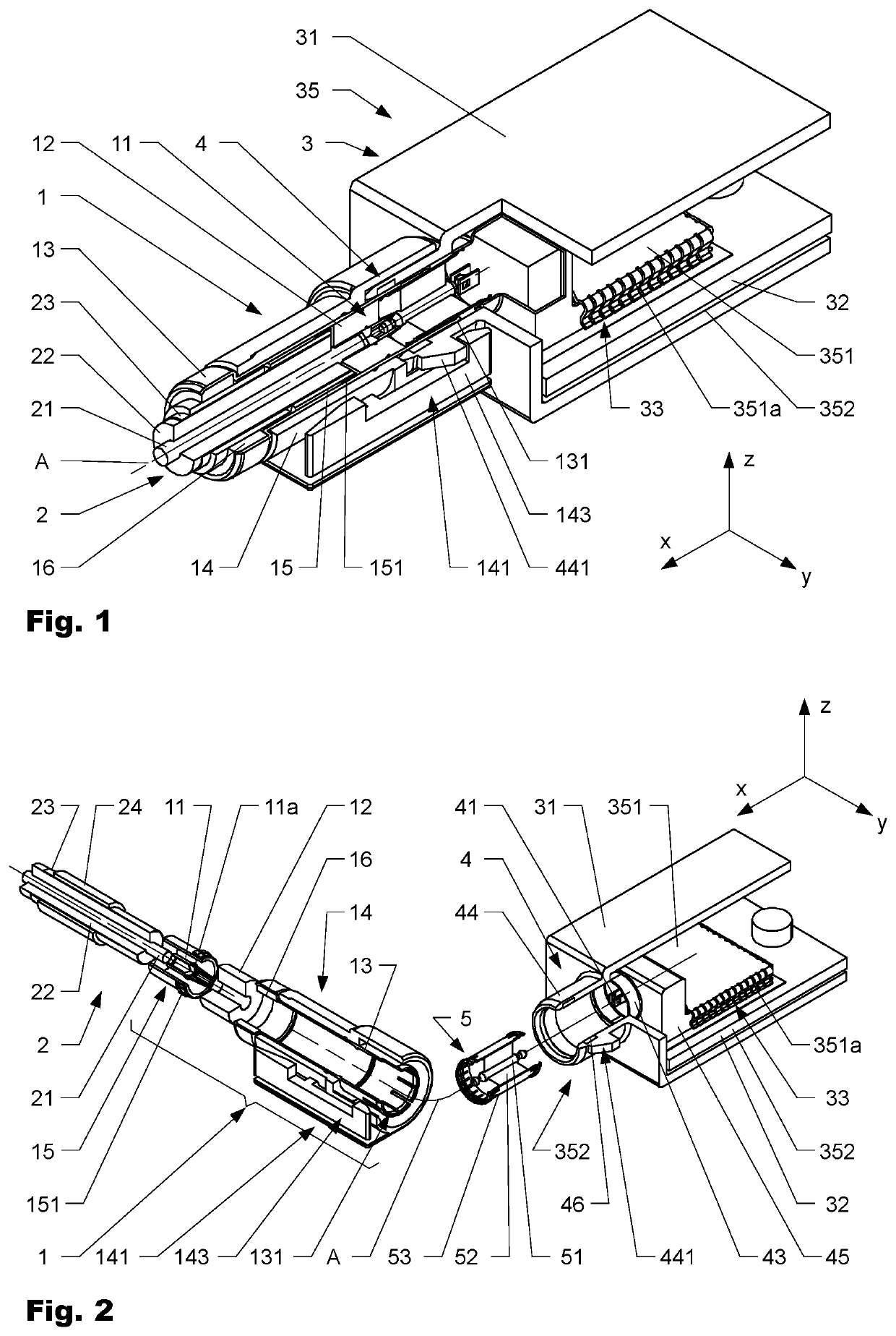
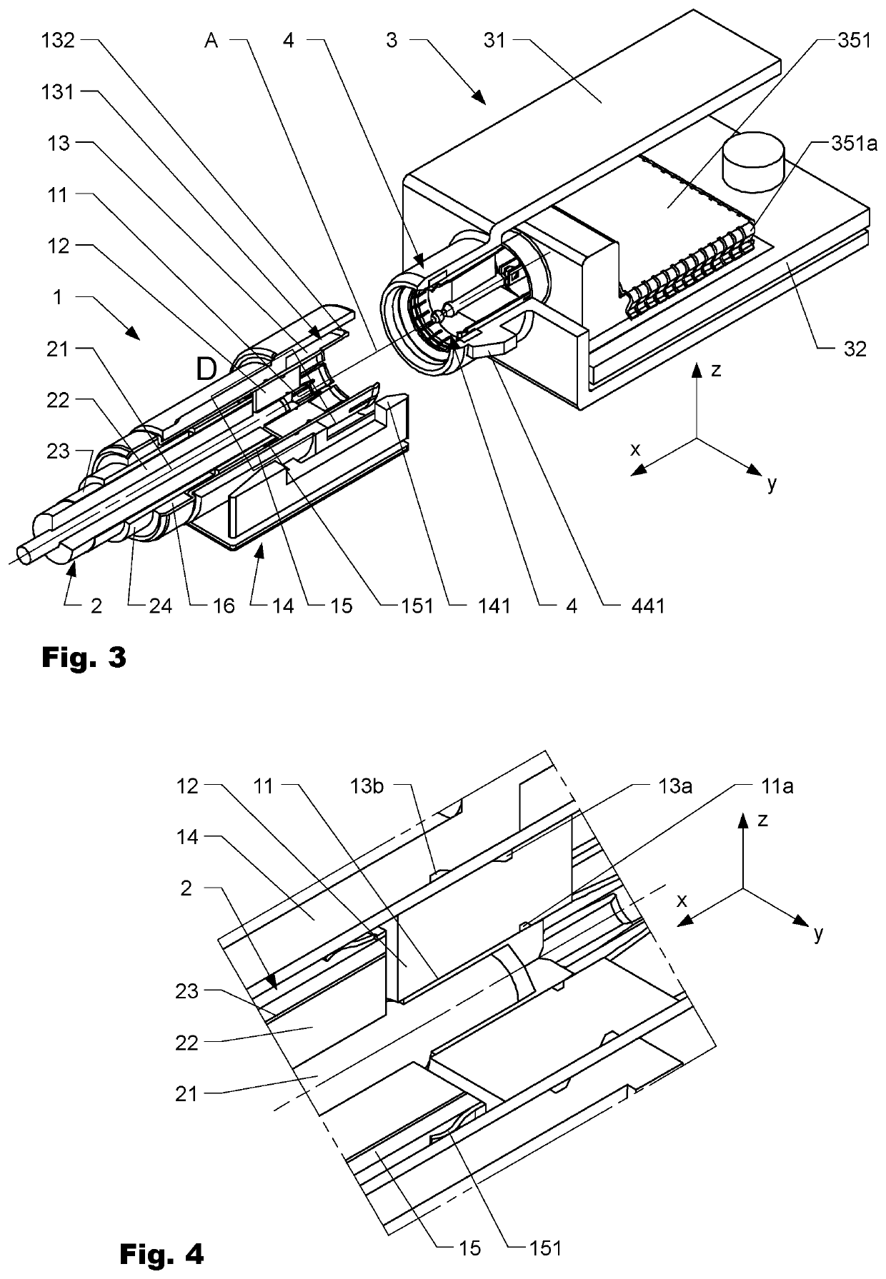
[0063]In the following, exemplary embodiments are explained in more detail with additional reference to the figures. It is to be understood that all directional terms, such as “top”, “bottom”, “left”, right”, “upper”, lower”, “above, “below”, etc. refer to the figures and are sole intended to improve the reader's understanding. They do not imply any particular orientation in use. The same applies to references to the coordinate system that is additionally shown in the figures.
[0064]A coaxial connector 1 (generally best seen in FIGS. 3, 4) comprises inner contact element 11 outer contact element 13, and insulating dielectric connector element 12 in coaxial arrangement with respect to connector axis A (parallel to x-axis). The connector axis A extends from the cable entry side on the left towards the coupling side on the right of coaxial connector 1. The inner contact element 11 is realized as jack with a tubular end section (not individually referenced) to receive a portion of an inn...
PUM
 Abstract
Description
Claims
Application Information
 - R&D
- Intellectual Property
- Life Sciences
- Materials
- Tech Scout
- Unparalleled Data Quality
- Higher Quality Content
- 60% Fewer Hallucinations
Browse by: Latest US Patents, China's latest patents, Technical Efficacy Thesaurus, Application Domain, Technology Topic, Popular Technical Reports.
© 2025 PatSnap. All rights reserved.Legal|Privacy policy|Modern Slavery Act Transparency Statement|Sitemap|About US| Contact US: help@patsnap.com


