Filter apparatus

a filter apparatus and filter technology, applied in the field of fluid filters, can solve the problems of inherently flow restrictive sintered filter components, harmful particles, and increased fluid flow resistance of sintered filters, and achieve the effect of reducing fluid pressure drop therethrough

Inactive Publication Date: 2005-08-02
IDEX HEALTH & SCI +1
View PDF17 Cites 28 Cited by
  • Summary
  • Abstract
  • Description
  • Claims
  • Application Information

AI Technical Summary

Benefits of technology

[0012]By means of the present invention, a filter apparatus for use in liquid chromatography systems is specifically configured and fabricated so as to inhibit the formation of gas bubbles in a chromatographic fluid flow stream passing therethrough, as well as to minimize fluid pressure drop therethrough. The filter apparatus of the present invention utilizes a relatively thin screened filter component that is preferably fabricated from a material which more preferentially wets the chromatographic fluid over air compared to fluoropolymers. The so-constructed mesh filter component is preferably operably positioned and secured and sealed in a housing adapted to operably receive chromatographic fluid transfer lines therein.

Problems solved by technology

Such unwanted debris includes, for example, particulate matter that may be harmful to delicate instrumentation incorporated in the respective chromatographic systems.
Such sintered filter components are inherently flow restrictive due to the low porosity formed by tortuous fluid paths and long fluid path lengths.
These sintered filters have a tendency to increase fluid flow resistance over time as a result of particulate matter being caught up in and blocking respective fluid flow paths.
The sintered materials are particularly susceptible to particulate matter retention due to the relatively long and narrow fluid flow paths extending therethrough.
Pre-pump flow restriction can cause pump and proportioning valve fluid starvation.
As stated above, an issue involving sintered filter materials is the increased flow restriction (back pressure) therethrough as a function of operating time.
It necessarily follows that fluid flow through the valve unit on a predetermined timed basis varies with operational time, thereby having a detrimental effect on fluid volume input accuracy.
An additional issue associated with the use of Teflon fluoropolymers in sintered filter components is the tendency of such components to foster an environment for the formation of gas bubbles that are transferred into the fluid stream flowing therethrough.
Gas bubbles entrained within chromatographic fluids are problematic in that such bubbles lead to inaccurate eluent proportioning, check valve death, measurement drift, and other analytical measurement errors.

Method used


Image

  • Filter apparatus
  • Filter apparatus
  • Filter apparatus

Examples


Embodiment Construction

[0024]The objects and advantages enumerated above together with other objects, features, and advances represented by the present invention will now be presented in terms of detailed embodiments described with reference to the attached drawing figures which are intended to be representative of various possible configurations of the invention. Other embodiments and aspects of the invention are recognized as being within the grasp of those having ordinary skill in the art.

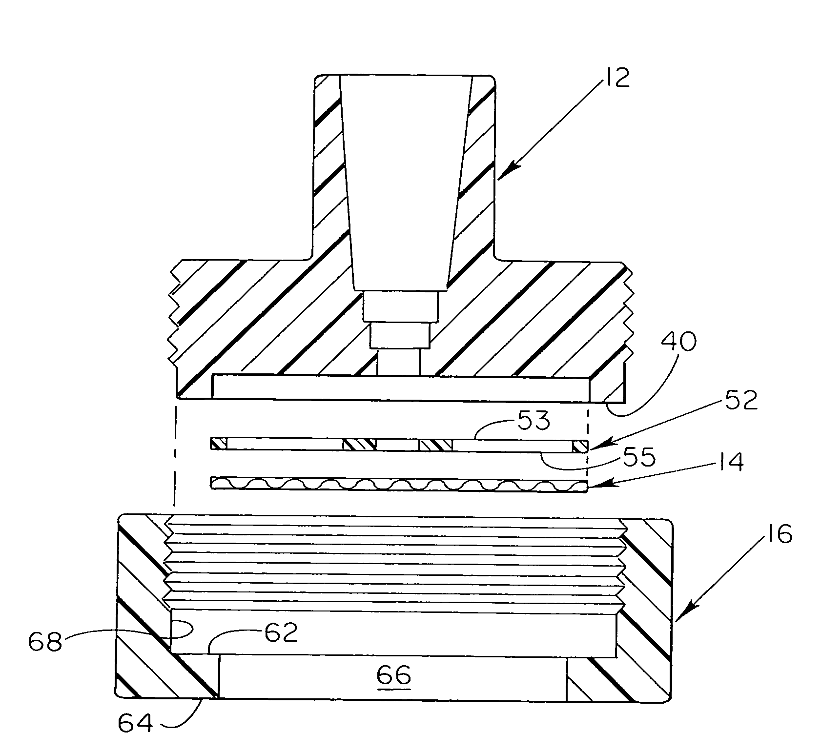
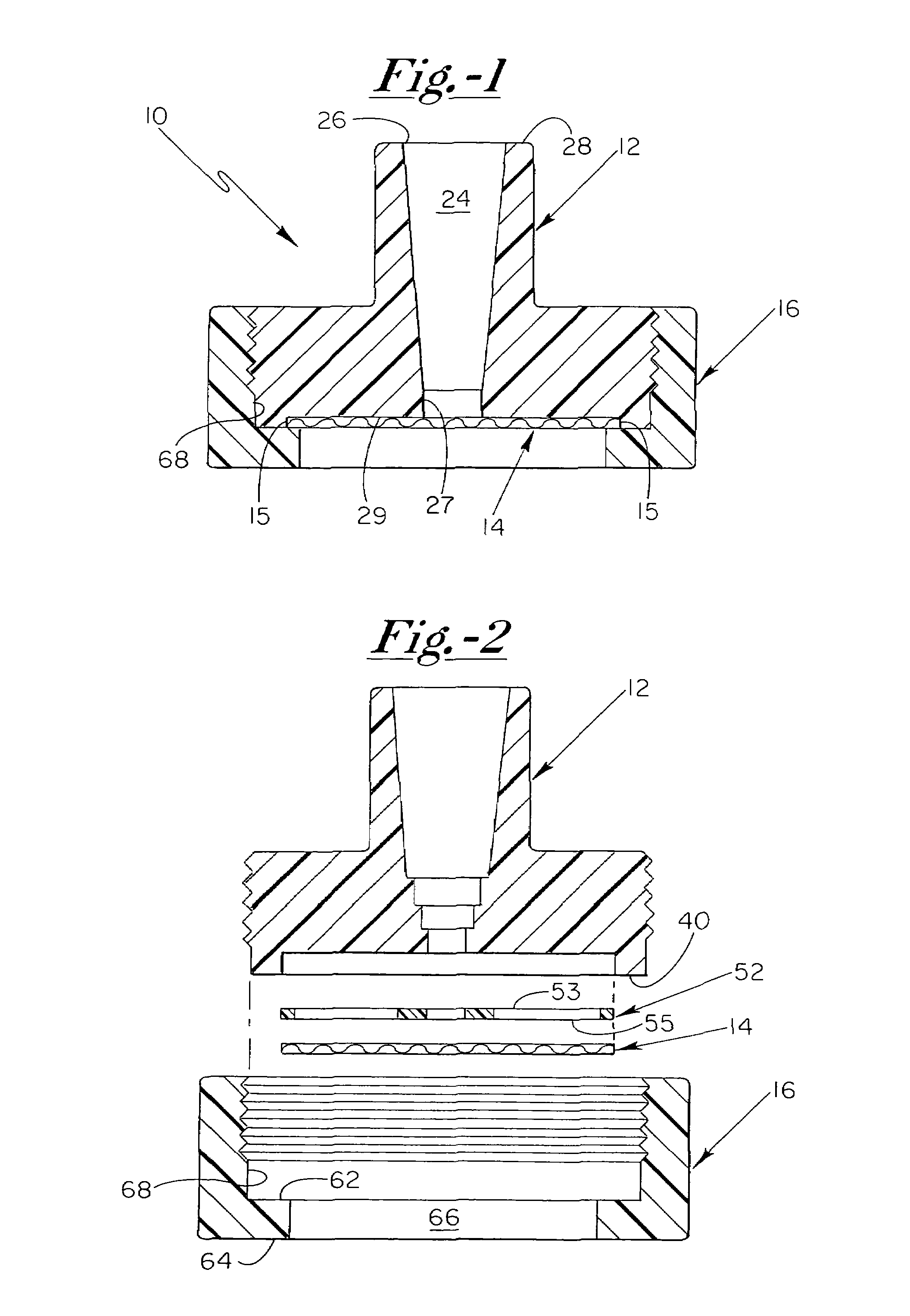
[0025]With reference now to the drawing figures, and first to FIG. 1, a filter apparatus 10 of the present invention includes a connection means 12, a filtering means 14, and a securement means 16 that is configured to operably secure and seal filtering means 14 within filter apparatus 10. Connection means 12, filtering means 14, and securement means 16 are preferably individual components that are configured to be selectively engageable with one another, though apparatus 10 may comprise a single component having filt...


PUM

PropertyMeasurementUnit
mean diameteraaaaaaaaaa
thicknessaaaaaaaaaa
diameteraaaaaaaaaa

Abstract

A filter apparatus for use in liquid chromatography systems includes a housing component having an open channel formed therethrough for operably receiving fluid transfer tubing in at least a first end thereof, a relatively thin mesh filter component, and a securement component configured to matingly engage with the housing such that the filter component is operably disposed and secured between the housing and the securement component adjacent to and superimposed over a second open end of the channel. The filter apparatus is thus adapted to operably filter chromatographic fluids being drawn through the channels from the second open end and into the fluid transfer tubing.

Description

FIELD OF THE INVENTION[0001]The present invention relates generally to fluid filters utilized in liquid chromatography systems, and more particularly to a low flow restriction mesh fluid filter that is particularly fabricated to eliminate capillary condensation of gas into the chromatographic fluids being drawn from a fluid reservoir into a liquid chromatography system.BACKGROUND OF THE INVENTION[0002]Liquid chromatography systems typically draw one or more chromatographic fluids therethrough from corresponding fluid reservoirs. In order to inhibit the infiltration of unwanted debris into the chromatographic system from the respective fluid reservoirs, filter components have been positioned in fluid transfer lines between the fluid reservoirs and the chromatographic system. Such unwanted debris includes, for example, particulate matter that may be harmful to delicate instrumentation incorporated in the respective chromatographic systems. Therefore, an important feature of liquid chr...

Claims


Application Information

Patent Timeline
Patent Type & Authority Patents(United States)
IPC IPC(8): B01D15/08B01D15/12G01N30/60
CPCB01D39/083B01D39/086G01N30/603B01D15/12B01D2239/0208B01D2239/1291
Inventor THOMPSON, JONATHANGERNER, YURISIMS, CARL W.
Owner IDEX HEALTH & SCI
Why Eureka
Try Eureka