Alternative state flow valve

a flow valve and alternative state technology, applied in the direction of valve sealing, spindle operation/release device, transportation and packaging, etc., can solve the problems of insufficient water distribution, insufficient spray distance, insufficient equilibrium pressure, etc., and achieve low cost, high fluid flow efficiency, economic advantage

Inactive Publication Date: 2014-06-17
AEROMASTER INNOVATIONS
View PDF55 Cites 0 Cited by
  • Summary
  • Abstract
  • Description
  • Claims
  • Application Information

AI Technical Summary

Benefits of technology

[0019]The present invention provides a sequencing valve that addresses these shortcomings. Specifically, the present invention provides a valve configured to operate with impurities in the fluid flow ranging in size from microscopic to objects as large as the conduit itself. The present invention provides a valve that has the same dimensions as an existing ½″ NPT close nipple, making it universally adaptable to all typical residential and commercial ornamental applications. The present invention also provides a valve that can be manufactured for low cost such that an economic advantage can be realized when a plurality of valves are used instead of a major redesign of the main supply conduits. Finally, the present invention provides a valve having a highly efficient fluid flow path in the open state thus minimizing the fluid pressure drop for high flow rates.
[0020]Improvements to the invention further disclosed and claimed herein provide a more robust design of the aforementioned sequencing valve that tolerates variations in the supply pressure by providing a damped response that requires persistent pressure changes to effect a change of state. In addition, they provide a more convenient embodiment of the aforementioned sequencing valve where the instant state can be altered from the top of the valve thus eliminating the need to remove the valve to reset the sequence state.

Problems solved by technology

A problem arises when the equilibrium pressure is insufficient to provide adequate velocity.
Inadequate velocity results in insufficient spray distance and thus inadequate water distribution.
The inadequate pressure is caused by a mismatch in the system.
Too many heads or heads that require high flow volume can over-burden the supply.
Alternately, too much restriction or flow distance between the supply and flow heads can compromise the capability of the supply.
Once a distribution problem is recognized, the solution alternatives are very limited.
This often fails to produce the desired results.
This results in additional loss of spray distance and thus introduces new distribution problems.
Two more difficult alternatives are to add a new circuit or improve the plumbing of the existing circuit.
Both of these alternatives require digging up the landscape areas that are receiving insufficient irrigation.
This fact, combined with high cost and excessive labor requirements, makes these alternatives unattractive.
Carver's valve contained design features which would have made it unreliable in service.
Such wear would lead to external leakage.
It is likely that impurities in the fluid would have caused frictional changes in the seals that would impede proper operation.
Perlis' valve had a critical flaw, however, wherein the pressure responsive piston relied upon a close fit within the valve body to prevent the fluid from passing the piston without actuating the valve.
This valve would have been very sensitive to impurities such as dirt or grit which would become lodged between the piston and the housing thus rendering the valve non-functional.
This method is undesirable because the design requires a predetermined flow rate to operate properly and necessarily causes a pressure loss as the fluid passes through.
It is large and complex and therefore cannot be retrofit into residential systems economically.
While this arrangement is widely accepted in the art of flow control valves, it is also well known to cause a relatively large pressure loss when the fluid flow rate through the valve is high compared to the port size.
Other prior art failed to fully address all of the shortcomings described here.
All of the above referenced patents suffer from one or more of the following shortcomings: (1) The pressure responsive and / or sequencing means is exposed to the fluid flow and is therefore sensitive to impurities in the fluid; (2) The size and / or complexity does not allow for economical retrofit within existing residential systems; and (3) The fluid flow path contains abrupt changes of cross sectional area and / or direction that lead to large pressure losses for high fluid flow rates.

Method used


Image

  • Alternative state flow valve
  • Alternative state flow valve
  • Alternative state flow valve

Examples


Embodiment Construction

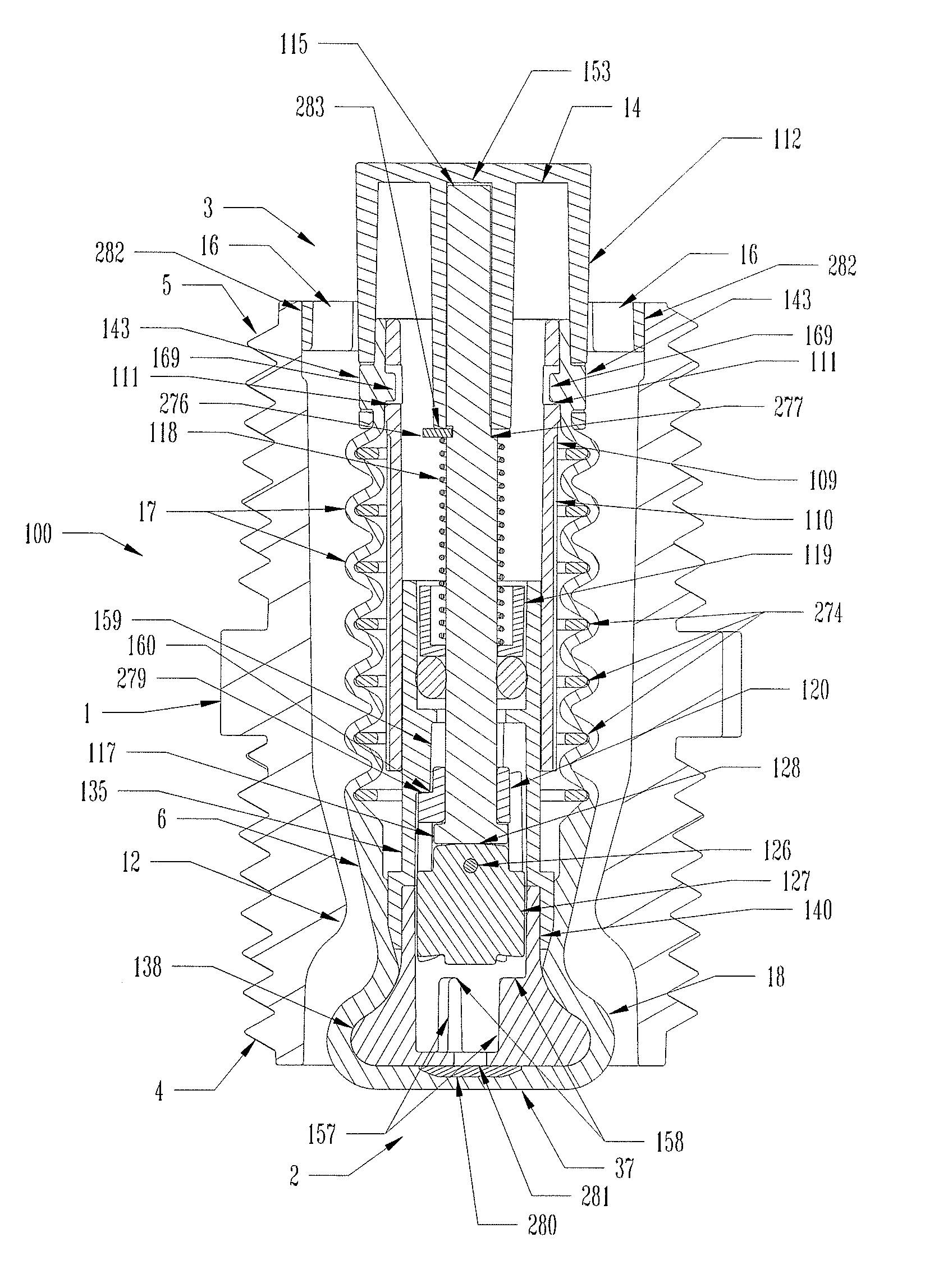
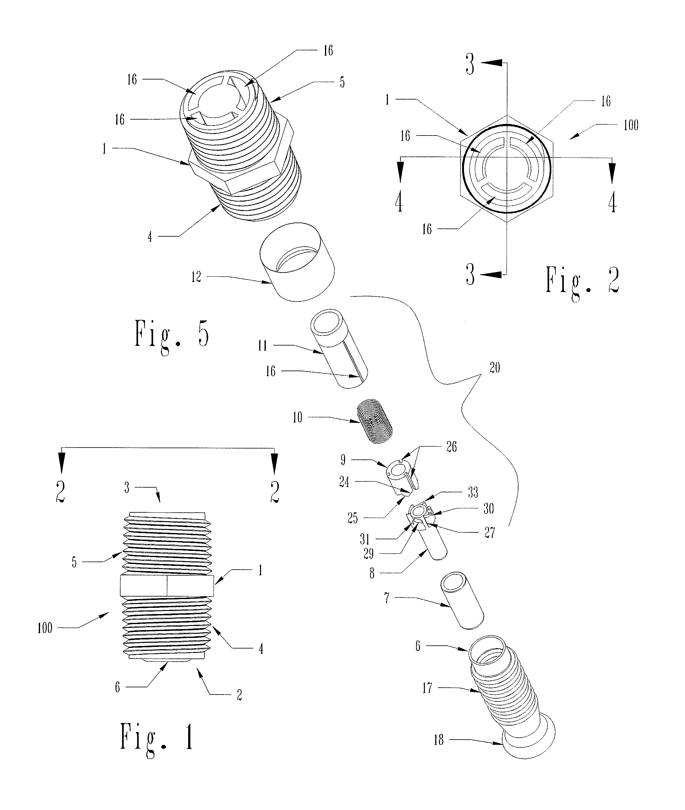
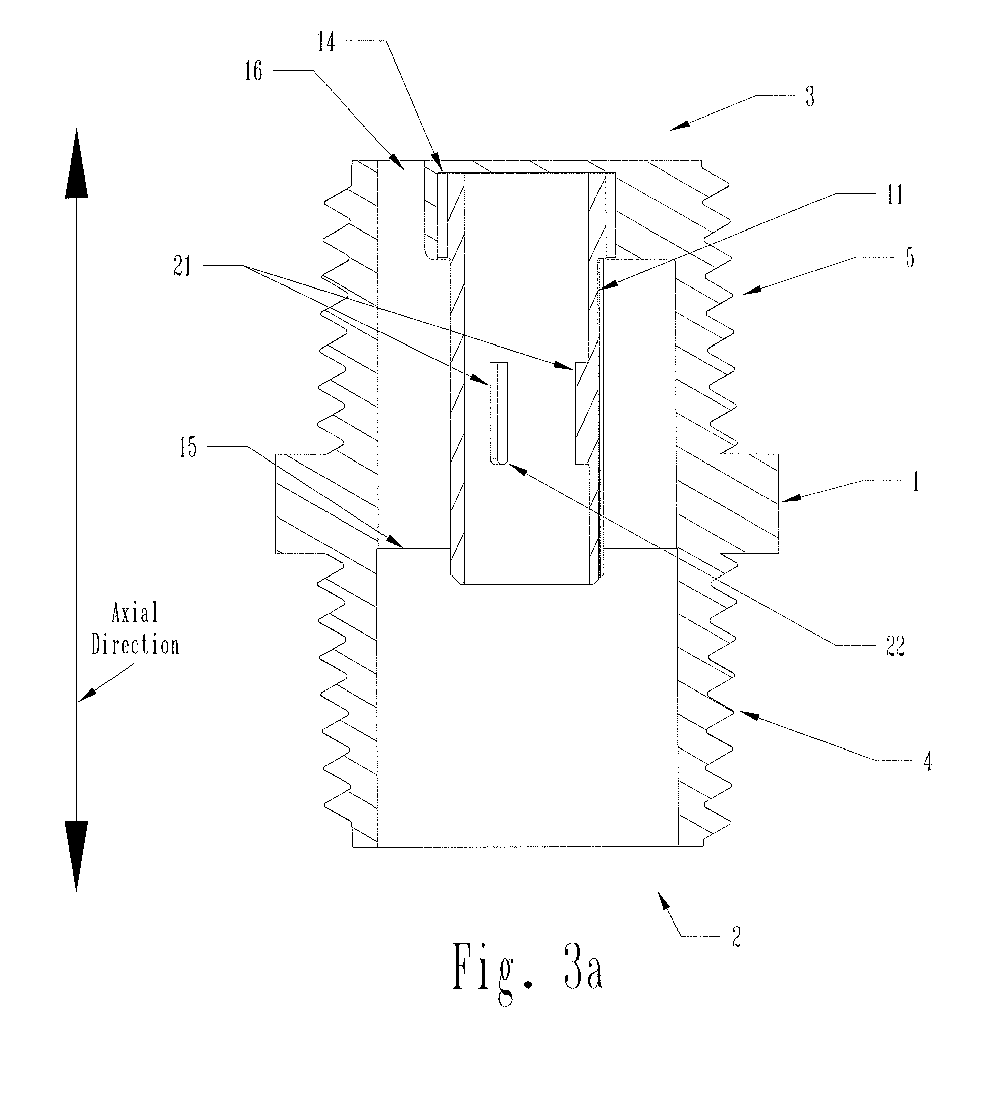
[0076]The present invention provides a low cost and convenient solution to the problem of improving irrigation sprinkler coverage. Referring to FIG. 7, the threaded pipe nipple that commonly attaches each spray head 101 to a main supply conduit 102 is replaced with an alternating fluid flow valve 100 (alternating fluid flow apparatus). Each time the main supply conduit 102 is pressurized, each valve 100 assumes either an open free flowing state or a closed non-flowing state. If half of the valves 100 are open and half of the valves 100 are closed, then the total usage of the spray heads is one half. This provides a higher pressure and thus better spray distance. Each time the pressure is removed and restored, the valves 100 change state. Thus, the valves 100 that were previously closed become open and vice versa. By simply pressurizing the main supply conduit 102 twice rather than once, all spray heads are activated with high pressure and adequate distribution is attained.

[0077]In m...


PUM


Abstract

An improved sequencing fluid control valve comprising a housing having inlet and outlet ports, a valve seat disposed within the housing, a collapsible valve member disposed within the housing and forming a chamber and a bulb. A sequencing means disposed within the chamber that controls the axial motion of the valve member in response to application of fluid pressure at the inlet such that the motion of valve member alternates between an open free flowing state and a closed restricted flow state. Housing and valve member cooperate in the open position to provide an annular flow path that does not require the fluid flow direction to substantially change while flowing from inlet to outlet. Housing and valve member bulb cooperate in the closed position to form a circumferential seal to restrict the fluid flow. Alternative embodiments including viscous damping means and variations on the housing mount are described.

Description

PRIORITY CLAIM[0001]This application is a Continuation-in-Part of U.S. application Ser. No. 12 / 435,271 filed on May 4, 2009, which application claims priority to U.S. Provisional Application No. 61 / 206,186, filed Jan. 28, 2009, and also claims priority to U.S. Provisional Application No. 61 / 216,920, filed May 22, 2009, the subject matter of which is incorporated herein in its entirety.FIELD OF THE INVENTION[0002]This invention relates generally to an improved valve configured to add new capability to fluid flow systems and, more specifically, to an improved valve that responds to periodic applications of pressure by alternating from a free flowing configuration to a restricted flow configuration.BACKGROUND OF THE INVENTION[0003]In many dry climates, distributed subterranean plumbing systems are used to supplement natural watering for landscape irrigation. These systems typically consist of one or more zonal fluid circuits each comprising a single control valve, a main supply conduit...

Claims


Application Information

Patent Timeline
Patent Type & Authority Patents(United States)
IPC IPC(8): B01D17/12
CPCF16K41/103Y10T137/86911Y10T137/86445Y10T137/7835Y10T137/86413Y10T137/6198Y10T137/2693Y10T137/86405Y10T137/86461
Inventor SPITZER, JEFFREY, J.
Owner AEROMASTER INNOVATIONS
Why Eureka
Try Eureka