Hydrodynamic brake

a brake and hydraulic technology, applied in the direction of rotary clutches, couplings, fluid couplings, etc., to achieve the effect of efficiently retarding the circulating air stream and reducing the velocity of the circulating air

Inactive Publication Date: 2005-08-02
SCANIA CV AB
View PDF10 Cites 5 Cited by
  • Summary
  • Abstract
  • Description
  • Claims
  • Application Information

AI Technical Summary

Benefits of technology

[0005]The object of the present invention is to provide a hydrodynamic brake comprising means, which in a simple and effective way reduces the circulation of air in the toroid-shaped space, which arises in the hydrodynamic brake when no brake action is desired to be obtained.
[0007]According to a preferred embodiment of the present invention, the second medium is arranged to be supplied in the form of at least one jet. The jet may have a suitable shape and a pressure, which actively reduces the direction of motion and the velocity of the air. Such jets should be supplied with a velocity of above 10 m / s in order to guarantee that they will be able to retard and penetrate the outermost air layer in the toroid-shaped space. Preferably, the velocity should be at least 20 mIs. Alternatively, the second medium may be supplied as a number of jets in order to obtain a more spread influence on the circulating air in the toroid-shaped space. Advantageously, the second medium is identical with the first medium in the brake. The first medium is usually an oil. Such an oil is, in most cases, also suitable as a medium for reducing the circulation of air in the toroid-shaped space. By using the same medium for preventing circulation of air as for providing a brake action, handling of the second medium is simplified. No special collecting containers for the second medium need be provided, for example.
[0009]According to another preferred embodiment of the present invention, the injection member may be arranged to inject the second medium from a radially inwardly located portion of the toroid-shaped space. The velocity of the circulating air is reduced in the passage from the stator to the rotor. Advantageously, the injection member is, in this case, provided is a shaft portion of the rotor and comprises an orifice in the bottom surface of the recess of the rotor. Advantageously, the second medium is supplied in a direction with an angle of 15° to 45° to a radial direction, which extends from the orifice of the injection member to a center in the toroid-shaped space. Supplying jets with a high pressure in an angle range of about 30° seems to be the most favorable for most efficiently retarding the circulating air stream at the same time as an effective medium mist is obtained in the toroid-shaped space. Suitably, the means comprises a plurality of injection members located both at radially outwardly and inwardly located portions and with constant intervals along the circular extension of the zoroid-shaped space. Thereby, the circulation of air may be counteracted effectively in the whole toroid-shaped space.

Problems solved by technology

Since the stator is immobile, it is relatively uncomplicated to provide an injection member in the stator for the supply of the second medium in the area.

Method used


Image

  • Hydrodynamic brake
  • Hydrodynamic brake
  • Hydrodynamic brake

Examples


Embodiment Construction

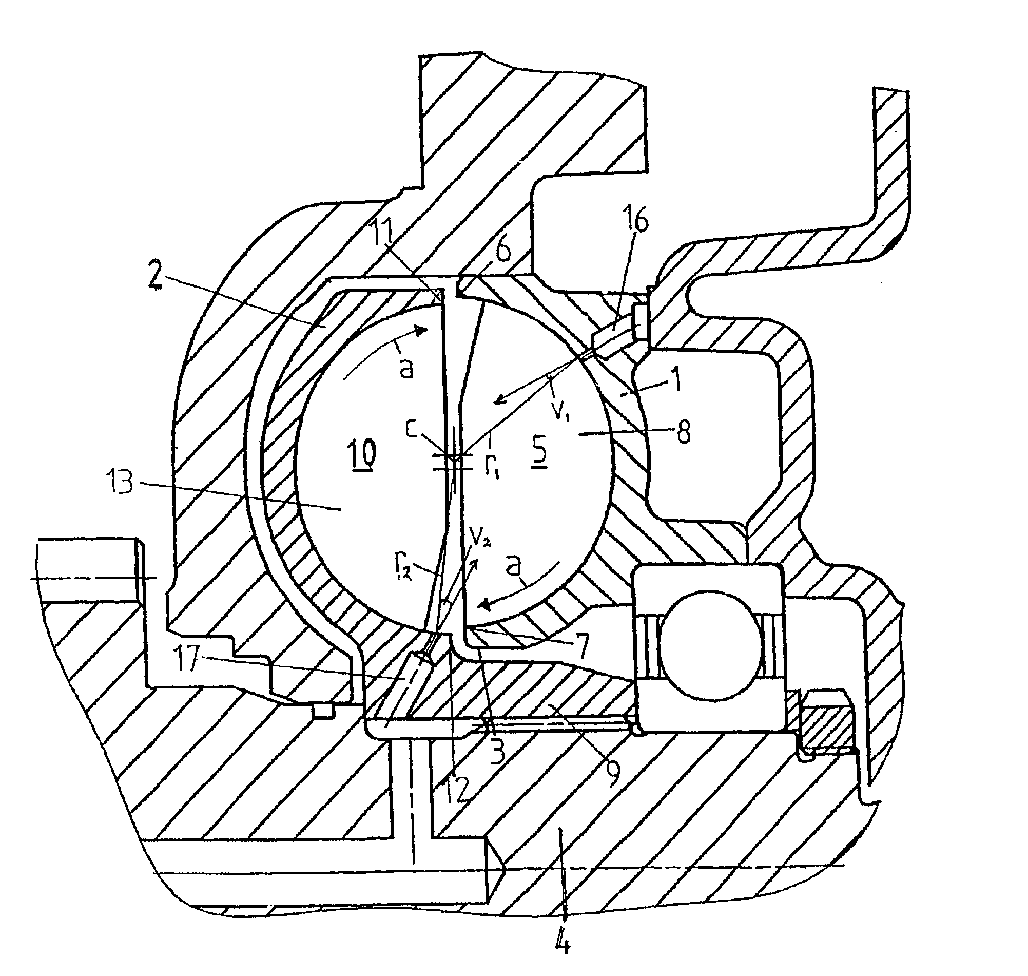
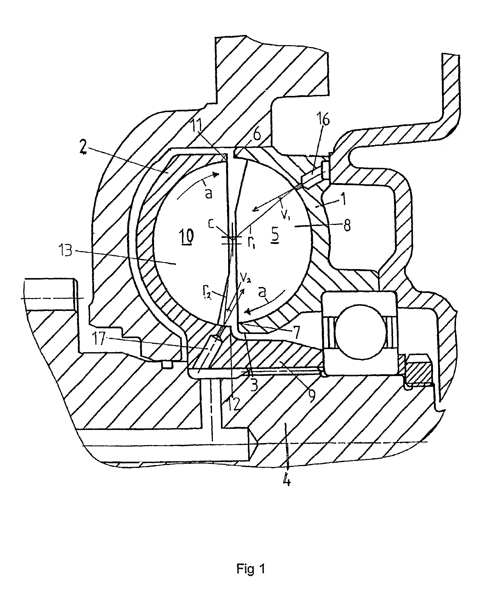
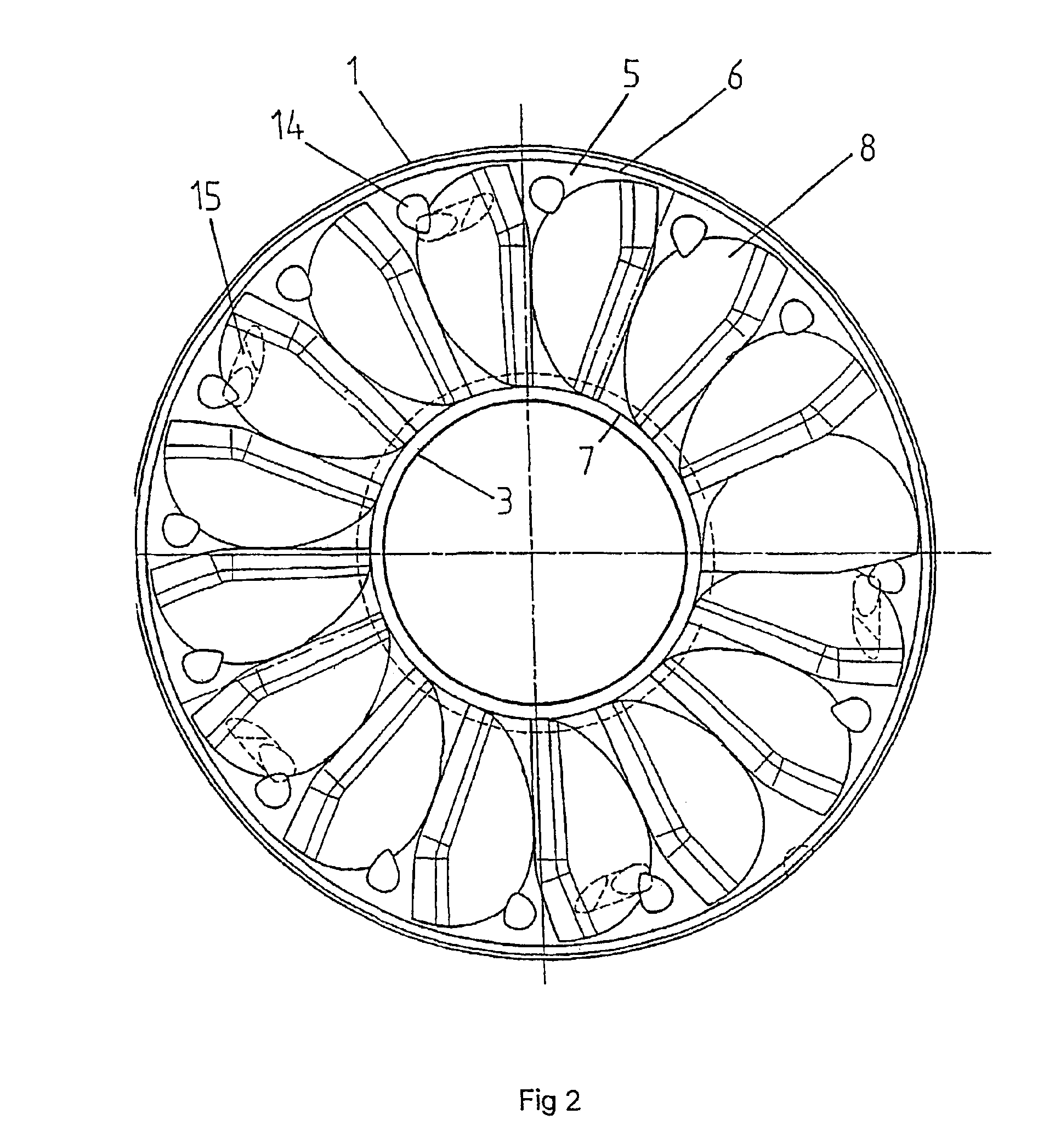
[0014]FIG. 1 shows a cross section through a portion of a hydrodynamic brake in form of a retarder of a motor driven vehicle. The retarder comprises a stator 1 and a rotor 2. The stator 1, which is shown separately in FIG. 2, comprises an annular body having an inner radial surface 3, which defines a circular opening. A rotatable shaft 4 extends through the circular opening of the stator 1. The rotatable shaft 4 is, via a transmission device, in connection with a driving shaft of the vehicle. The stator 1 is fixed in the vehicle in a suitable way. The body of the stator 1 comprises an annular recess 5, which in the mounted state of the retarder, extends around the rotatable shaft 4. The annular recess 5 is restricted in a radial direction outwards by an outer edge 6 and in a radial direction inwards by an inner edge 7. A number of vanes 8 are provided with uniform intervals along the circular extension of the annular recess 5. The vanes 8 have a substantially radial extension throug...


PUM


Abstract

A hydrodynamic brake, which comprises a stator and a rotor which are coaxial and have respective opposed annular recesses which open toward each other to form a toroid-shaped space. A first medium is supplied to the space for providing braking action during rotation of the rotor. At least one injection member is arranged to supply a second medium to the toroid-shaped space for reducing the circulation of air in the toroid-shaped space when no brake action is desired. The second medium is supplied at at least one location to the toroid-shaped space with a pressure and in a direction which at least partly is directed towards the principal flow direction of the circulating air.

Description

BACKGROUND OF THE INVENTION AND PRIOR ART[0001]The present invention relates to a hydrodynamic brake which reduces the circulation of air in the space in the brake.[0002]In the use of hydrodynamic brakes, such as retarders in vehicles, a certain brake action always arises during the propulsion of the vehicle as a consequence of the rotation of the rotor with a driving shaft of the vehicle. This brake action is caused by the air in the toroid-shaped space being forced to circulate. The circulating air provides a brake action in a way corresponding to the action of the introducable medium when the air circulates in the toroid-shaped space. The supplied medium is usually an oil having suitable properties. Although the density of the air is only a fraction of the density of the oil, the brake action arising hereby is not entirely negligible. The fuel consumption of a vehicle having a retarder therefore becomes unnecessarily high.[0003]In order to reduce this circulation of air in the to...

Claims


Application Information

Patent Timeline
Patent Type & Authority Patents(United States)
IPC IPC(8): F16D57/04F16D57/00
CPCF16D57/005F16D57/04
Inventor JONSSON, HANSARNE, JOHNNYHAGEN, TORGERKJELL, ANDERS
Owner SCANIA CV AB
Why Eureka
Try Eureka