Optical fiber having low non-linearity for WDM transmission

a technology of optical fiber and non-linearity, applied in the direction of fiber transmission, transmission, lasers, etc., can solve the problems of large effective area fibers, unable to achieve optimum decrease in , prone to increase fiber loss of refractive index-modifying dopants, so as to increase the refractive index, increase the non-linearity of glass, and reduce the effect o

Inactive Publication Date: 2005-07-26
PRYSMIAN CAVI E SISTEMI ENERGIA
View PDF8 Cites 8 Cited by
  • Summary
  • Abstract
  • Description
  • Claims
  • Application Information

AI Technical Summary

Benefits of technology

[0018]Applicants have noticed that the distribution of refractive-index-modifying dopants in the fiber cross-section has a significant impact on the fiber non-linearity characteristics. Applicants have determined that the non-linear index n2 contributes to the non-linearity coefficient γ with a constant term, due to pure silica and with a radially varying term, proportional to the concentration of index-modifying dopants. Dopants that are added to pure silica glass to increase the refractive index (e.g., GeO2) or to decrease it (e.g., fluorine) both tend to increase the glass non-linearity beyond the non-linearity value of pure silica. Applicants have found that known large-effective-area fibers, while achieving an overall increase in effective area, fail to achieve an optimum decrease in γ, due to the effect of dopants in areas of the fiber cross-section where the optical field has a relatively high intensity.

Problems solved by technology

Applicants have found that known large-effective-area fibers, while achieving an overall increase in effective area, fail to achieve an optimum decrease in γ, due to the effect of dopants in areas of the fiber cross-section where the optical field has a relatively high intensity.
Furthermore, Applicants have noticed that refractive-index-modifying-dopants tend to increase fiber loss, in particular due to an increased scattering loss.

Method used


Image

  • Optical fiber having low non-linearity for WDM transmission
  • Optical fiber having low non-linearity for WDM transmission
  • Optical fiber having low non-linearity for WDM transmission

Examples


first embodiment

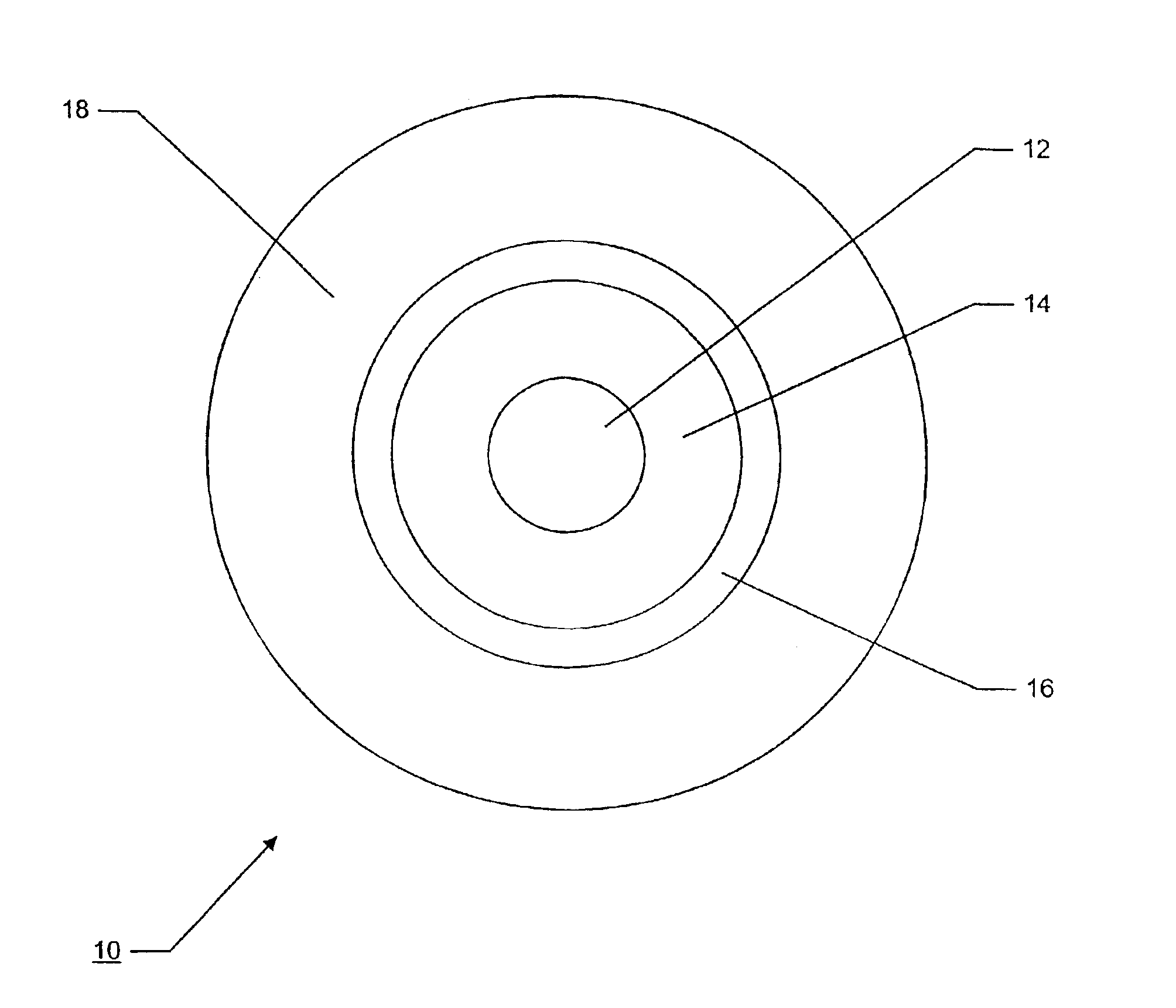
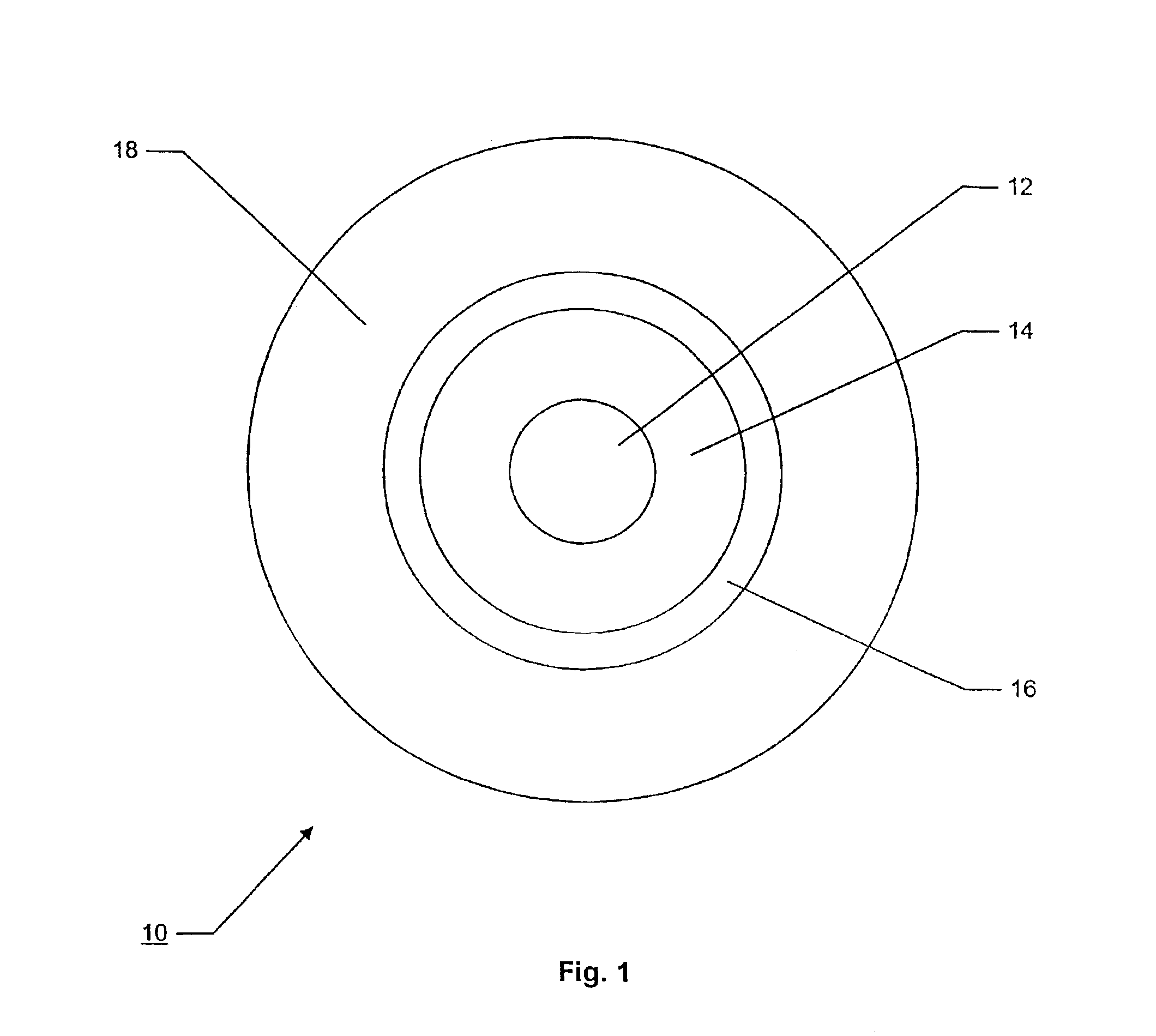
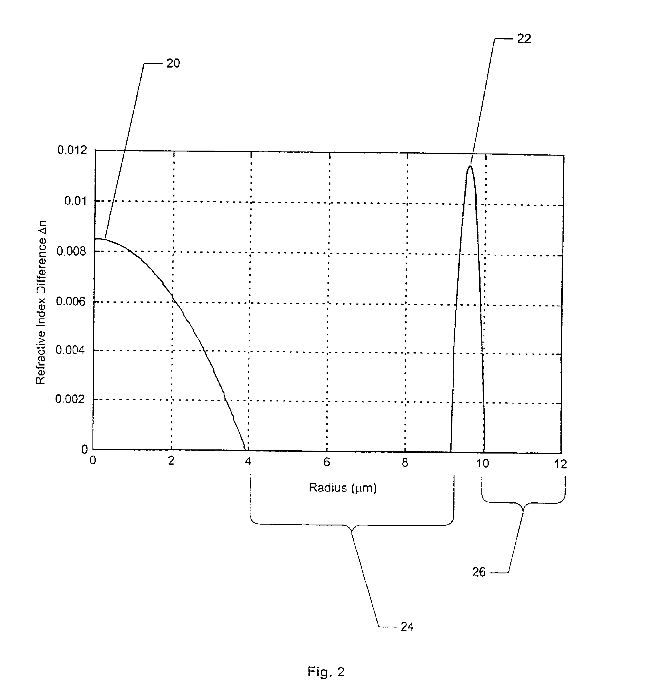
[0052]FIG. 2 illustrates a refractive index profile across the radius of fiber 10 for the present invention. As generally shown, fiber 10 has two refractive index peaks 20 and 22 positioned respectively within inner core 12 and second layer 16. First layer 14, which is disposed radially between inner core 12 and second layer 16, provides a refractive index dip relative to its two adjacent layers 12 and 16. Consequently, the combination of inner core 12, first layer 14, and second layer 16 generally provides an optical fiber profile having a segmented core with an outer layer having the highest index of refraction within the cross-section-of the fiber.

[0053]As shown in FIG. 2, according to a first embodiment of the present invention, inner core 12 has a radius r1 that is about 3.6 μm to 4.2 μm, but preferably is about 3.9 μm. Between the center of the fiber and the radial position at 3.9 μm, inner core 12 includes a refractive-index-increasing dopant such as GeO2 or the like that pro...

second embodiment

[0081]FIG. 9 illustrates the present invention for optical fiber 10 of FIG. 1. In this second embodiment, inner core 12 has a radius r1 that is about 2.3 μm to 3.6 μm, but preferably is about 2.77 μm. Between the center of the fiber and the radial position at 2.77 μm, inner core 12 includes one or more refractive-index-increasing dopants, such as GeO2 or the like, that produce a peak index of refraction at or near the axial center of fiber 10 and a minimum for the inner core at its outer radius. At the peak, the index of refraction Δn1 for inner core 12 in the second embodiment is about 0.010 to about 0.012, and preferably is about 0.0113. As with the first embodiment, the concentration of the refractive-index-modifying dopant in the core 12 decreases from the center to the outer radius at about 2.77 μm in a manner to produce a profile having a profile α of about 1.4 to about 3.0, but preferably of about 2.42. First glass layer 14 in the second embodiment has a substantially constan...

third embodiment

[0101]Second Layer Refractive Index Difference Δn3=0.0129. Of course, variations from these optimal structural values do not alter their general inventive features. Fiber 10 according to the present invention advantageously obtains the following optimal optical characteristics (at a wavelength of 1550 nm):

[0102]Dispersion=3.4 ps / nm / km

[0103]Dispersion Slope=0.11 ps / nm2 / km

[0104]Mode Field Diameter=9.95 μm

[0105]Effective Area=90 μm2

[0106]γ=1.00 W−1km−1. The third embodiment for fiber 10 having the above-listed optical characteristics provides acceptable conditions for the transmission in both solitons and non-soliton WDM systems.

[0107]FIG. 11 illustrates a fourth refractive index profile for optical fiber 10 that generates optical characteristics of nonzero positive dispersion. The physical characteristics of the inventive fiber of FIG. 11 include a radius r1 for inner core 12 of about 3.2 μm, an index of refraction profile α for inner core 12 of about 2.9, a maximum refractive index ...


PUM


Abstract

An optical transmission fiber has a refractive index profile with an area of increased index of refraction at the inner core of the fiber, an annular region positioned radially outward from the inner core with an index of refraction exceeding the index of the inner core, and at least a low dopant content region in a cross-sectional region between the inner core and the annular region. A low loss cladding layer surrounds the core region. The optical transmission fiber with this segmented core profile provides a high effective area, low non-linearity coefficient, nonzero dispersion, and relatively flat dispersion slope.

Description

[0001]This is a continuation of Application No. 09 / 984,170, filed Oct. 29, 2001, now U.S. Pat. No. 6,507,689 which is a continuation of Application No. 09 / 335,509, filed Jun. 18, 1999, now U.S. Pat. No. 6,321,016 which claims priority based on European Patent Application No. 98 111 292.3, filed Jun. 19, 1998, and claims the benefit of U.S. provisional application no. 60 / 090,791, filed Jun. 25, 1998, all of which are incorporated herein by reference.BACKGROUND OF THE INVENTION[0002]The present invention relates generally to an optical transmission fiber that has improved characteristics for minimizing non-linear effects, and specifically to an optical fiber for use in a wavelength-division-multiplexing (WDM) system that has two refractive index peaks with the maximum index of refraction difference located in an outer core region.[0003]In optical communication systems, non-linear optical effects are known to degrade the quality of transmission along standard transmission optical fiber...

Claims


Application Information

Patent Timeline
Patent Type & Authority Patents(United States)
IPC IPC(8): G02B6/02
CPCG02B6/02009G02B6/03644G02B6/02219G02B6/03694
Inventor TIRLONI, BARTOLOMEO ITALOSARTORI, FRANCESCO GABRIELESARCHI, DAVIDEROBA, GIACOMO STEFANO
Owner PRYSMIAN CAVI E SISTEMI ENERGIA
Why Eureka
Try Eureka