
Raised on-chip inductor and method of manufacturing same

a technology of inductor and on-chip, which is applied in the direction of magnets, inductances, magnetic bodies, etc., can solve the problems of bending torque on the magnetic layer, and achieve the effect of less susceptible to loss and parasitic effects, and small footprin

Inactive Publication Date: 2005-07-26
THE BOARD OF TRUSTEES OF THE UNIV OF ILLINOIS
View PDF8 Cites 19 Cited by
  • Summary
  • Abstract
  • Description
  • Claims
  • Application Information

AI Technical Summary

Benefits of technology

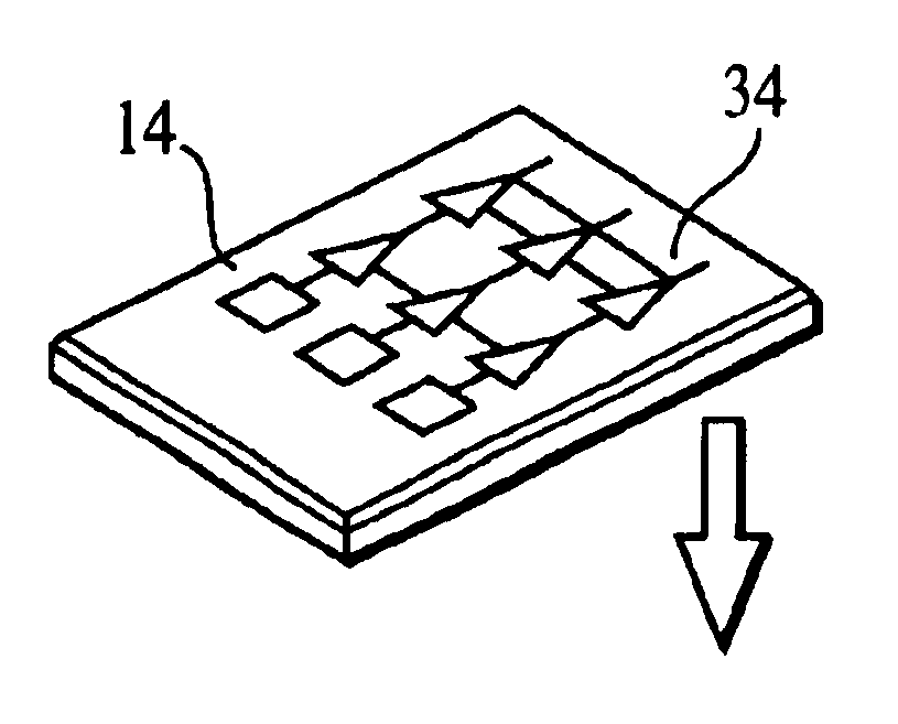
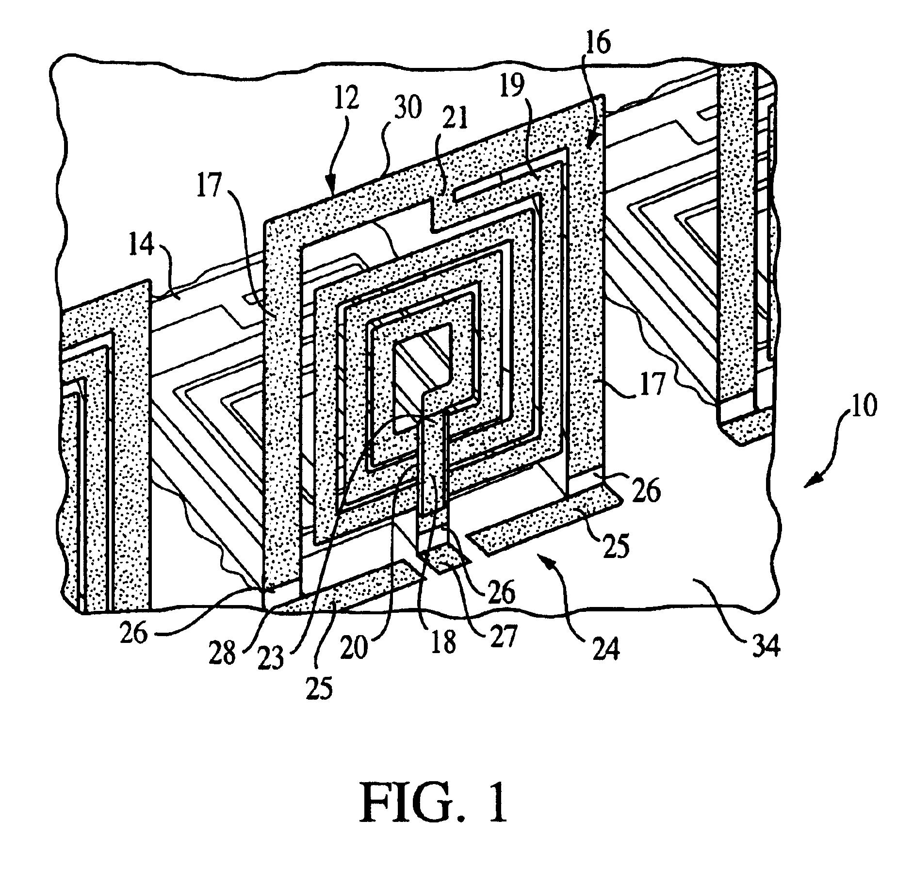
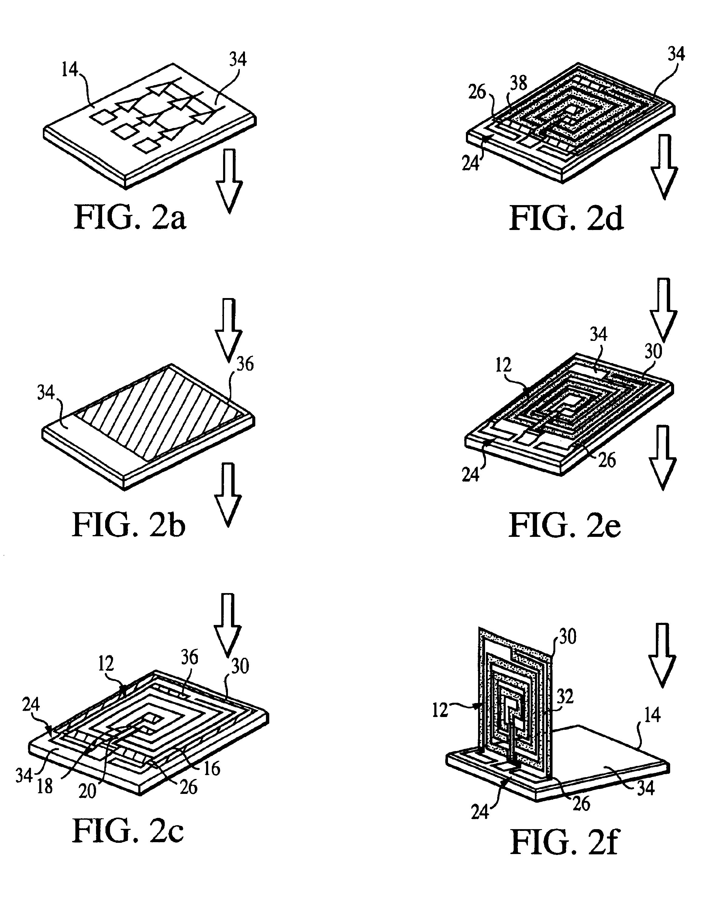
"The present invention provides an integrated circuit with a raised on-chip inductor. The inductor is fabricated on a substrate and then lifted off to a raised position using a magnetic field. The inductor is secured to the substrate using an anchoring extremity that also acts as an electrical lead. The plastic bending region of the inductor undergoes plastic deformation during the lifting process, allowing the inductor to remain at a raised rest angle after the magnetic field is removed. The raised on-chip inductor is much less susceptible to loss and parasitic effects from the substrate and has a significantly smaller footprint than conventional inductors. The method can also be used to raise other microfabricated components by forming them on a sacrificial layer and removing the sacrificial layer."

Problems solved by technology

This creates a bending torque on the magnetic layer.

Method used


Image

  • Raised on-chip inductor and method of manufacturing same
  • Raised on-chip inductor and method of manufacturing same
  • Raised on-chip inductor and method of manufacturing same

Examples


Embodiment Construction

[0015]The present invention provides a raised inductor arranged at an angle with respect to the substrate that hosts it, and methods for producing the inductor. A preferred embodiment of the inductor includes at least a first conductor. The first conductor is raised with respect to the substrate, and supported by an anchoring extremity, which is preferably disposed at a foot of the inductor. As used herein, the term “raised” means that the inductor is anchored to the substrate, or supported, by the anchoring extremity but is otherwise lifted, standing, or angled with respect to the surface of the substrate.

[0016]According to a preferred process of fabricating the inductor, a planar inductor that is made of a ductile material is fabricated onto a substrate of a chip. Preferably, the ductile material can be, but is not limited to, gold, aluminum, or copper. The planar inductor includes at least a first conductor. As fabricated, the first conductor, except for the anchoring extremity, ...


PUM

PropertyMeasurementUnit
thickness tpaaaaaaaaaa
bending angleaaaaaaaaaa

Abstract

A raised on-chip planar inductor. An inductor is fabricated on a substrate. The inductor, except for an anchoring extremity, is lifted from the substrate, preferably by application of a magnetic field to a magnetic layer formed on the inductor. The lifting of the inductor deforms a plastic bending region. After the magnetic field is removed, the inductor remains raised with respect to the substrate.

Description

REFERENCE TO RELATED APPLICATIONS[0001]This application claims the benefit of U.S. Provisional Application No. 60 / 292,963, filed May 23, 2001, under 35 U.S.C. §119.STATEMENT OF GOVERNMENT INTEREST[0002]This invention was made with government assistance from the Defense Advanced Research Program Agency (DARPA) under Grant No. F30602-97-2-2038. The government has certain rights in this invention.FIELD OF THE INVENTION[0003]The present invention relates generally to the field of fabrication of on-chip components for integrated circuits.BACKGROUND OF THE INVENTION[0004]High-performance on-chip inductors are increasingly needed for a wide range of environments, such as wireless communication systems and micro-electromechanical systems (MEMS). Planar coil inductors with moderate quality factor (Q) can be integrated with other radio frequency (RF) circuits by using standard integrated circuit (IC) fabrication processes. The effectiveness of these on-chip inductors in RF systems and other e...

Claims


Application Information

Patent Timeline
Patent Type & Authority Patents(United States)
IPC IPC(8): H01F17/00H01F41/04H01L23/52H01L23/522H01L23/58H01L23/66H01L27/08
CPCH01F17/0006H01F41/041H01L23/5227H01L23/66H01L27/08Y10T29/4902H01L2924/0002H01L2924/19104Y10T29/49071H01L2924/00
Inventor ZOU, JUNLIU, CHANGSCHUTT-AINE, JOSE
Owner THE BOARD OF TRUSTEES OF THE UNIV OF ILLINOIS
Learn More