
Sampling packets for network monitoring

a network monitoring and packet sampling technology, applied in the field of network monitoring, can solve the problems of increasing the processing required for each packet, the bandwidth and wire speed of the network interface is rapidly increasing, and the inability to monitor network traffic is not keeping up with the amount and speed of the network traffic itself, so as to achieve relatively little computational load per packet

Inactive Publication Date: 2005-07-19
CISCO TECH INC
View PDF232 Cites 82 Cited by
  • Summary
  • Abstract
  • Description
  • Claims
  • Application Information

AI Technical Summary

Benefits of technology

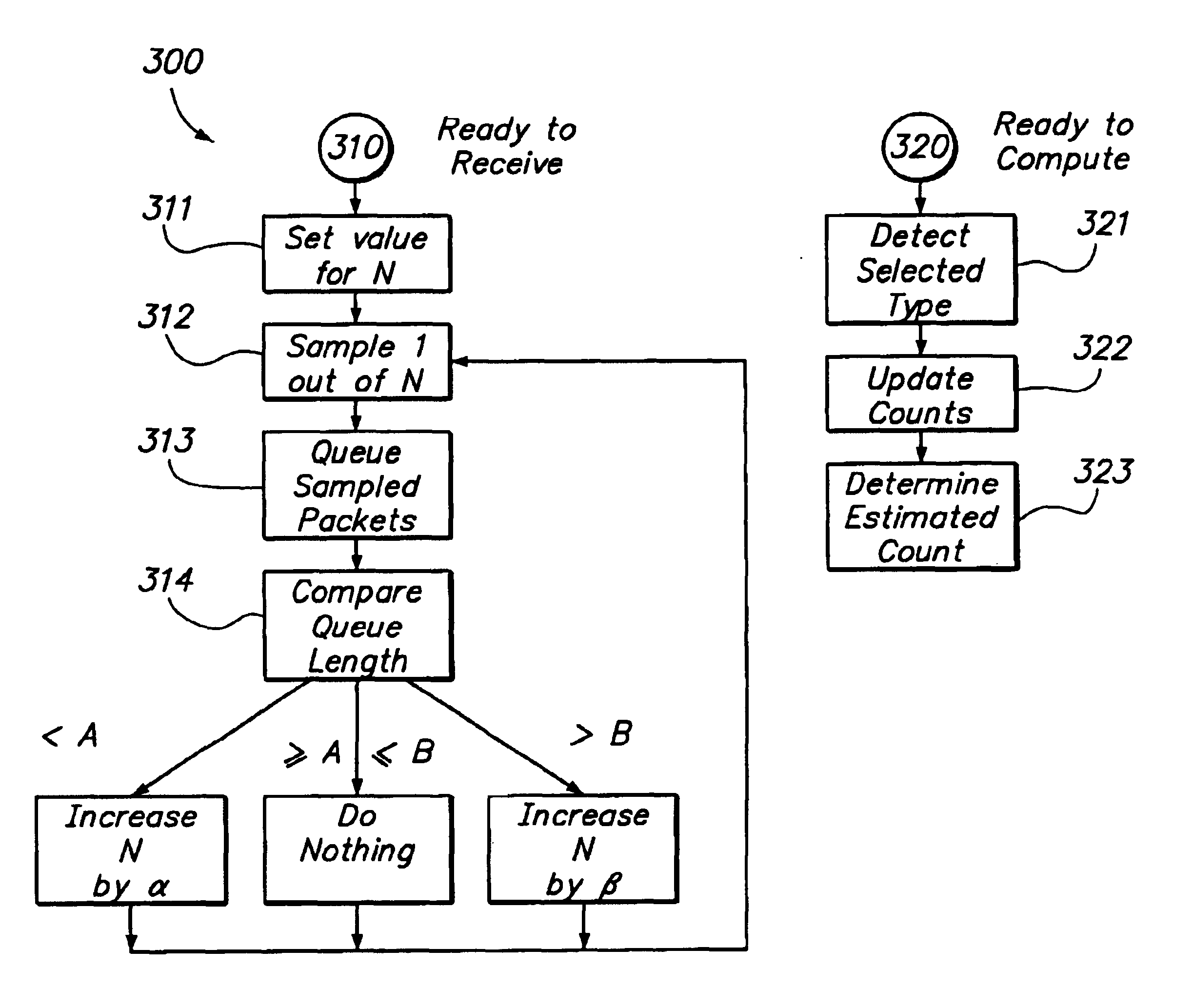
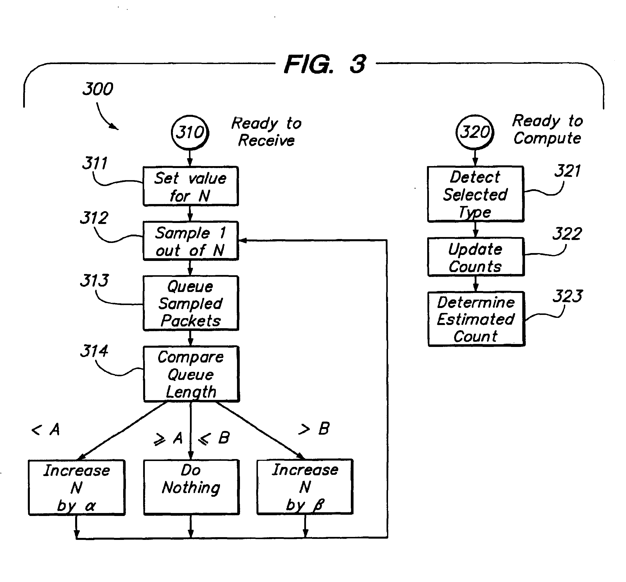
[0013]In a preferred embodiment, the measurement technique also determines an error range and a measure of confidence that the actual frequency is within the error range of the measured frequency. The system can detect packets of multiple selected types, and provide measured frequencies and error ranges for all of the multiple selected types concurrently. Also, the measurement technique is selected so as to impose relatively little computational load per packet.

Problems solved by technology

One problem in the known art is that ability to monitor network traffic is not keeping up with the amount and speed of the network traffic itself.
First, more recent versions of RMON result in an increase in the processing required for each packet.
Third, the bandwidth and wire speed of network interfaces is rapidly increasing due to advances in technology.
All three of these effects require additional processing power in the monitoring device.
However, these techniques suffer from several drawbacks.
First, estimated frequency measurement for relatively in-frequent events can be subject to error and inaccuracy.
Second, processor load for the monitoring device can vary wildly in response to network traffic load.
When network traffic is relatively frequent, processor load is relatively heavy, and the monitoring device can fail to keep up with the network traffic.
When network traffic is relatively infrequent, processor load is relatively light, and the monitoring device can be underused.

Method used


Image

  • Sampling packets for network monitoring
  • Sampling packets for network monitoring
  • Sampling packets for network monitoring

Examples


Embodiment Construction

[0017]In the following description, a preferred embodiment of the invention is described with regard to preferred process steps and data structures. Those skilled in the art would recognize after perusal of this application that embodiments of the invention can be implemented using circuits adapted to particular process steps and data structures described herein, and that implementation of the process steps and data structures described herein would not require undue experimentation or further invention.

Sampling System Elements

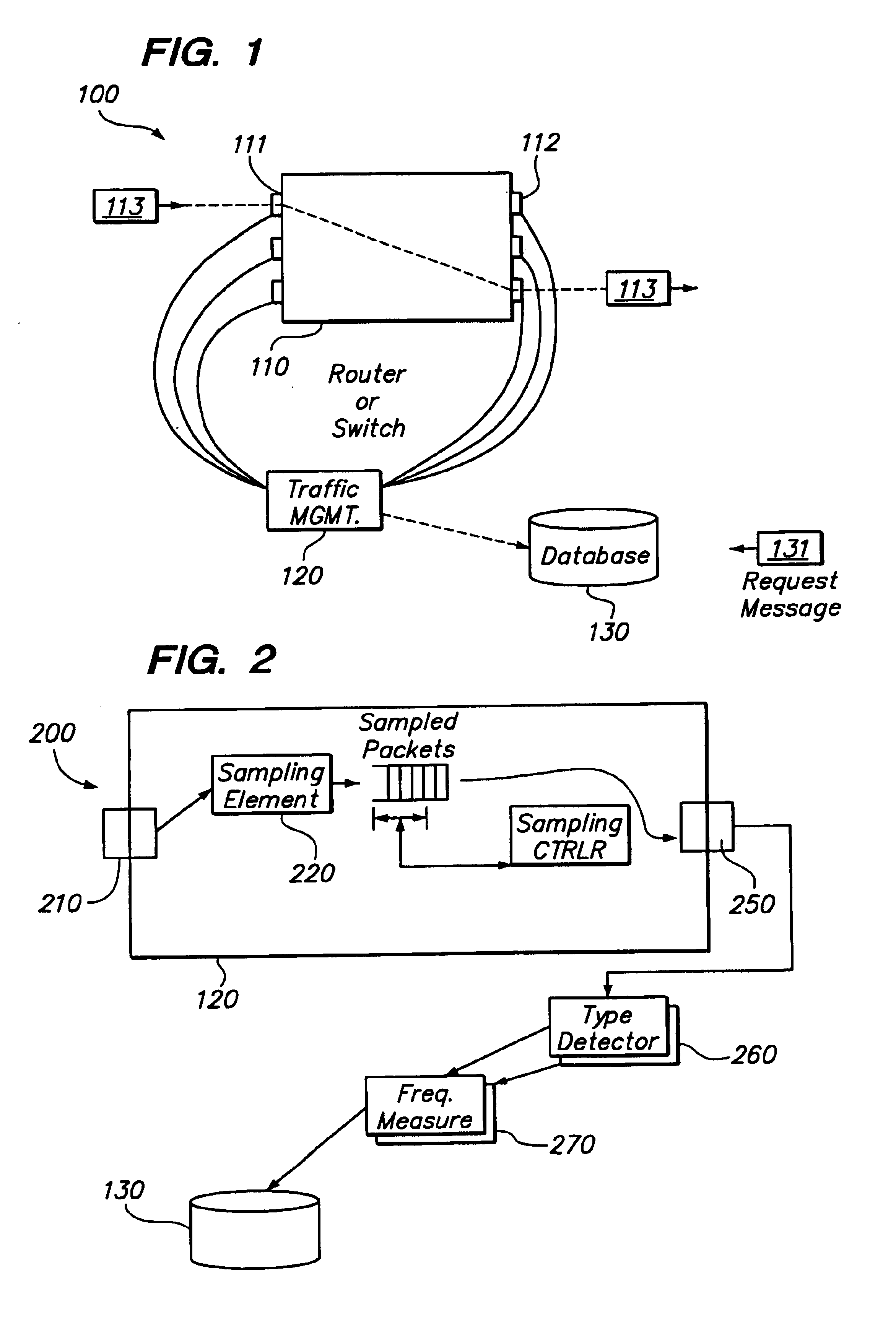
[0018]FIG. 1 shows a block diagram of a system for collecting information about packet traffic.

[0019]A system 100 for collecting information about packet traffic includes a packet router or packet switch 110, a traffic management element 120, and a traffic information database 130.

[0020]The packet switch 110 includes a plurality of input interfaces 111 and output interfaces 112. The packet switch 110 it is disposed to receive a sequence of packets 113 at one o...


PUM


Abstract

The invention provides a method and system for collecting aggregate information about network traffic, while maintaining processor load relatively constant despite substantial variation in network traffic, and capable of substantially accurate frequency measurement even for relatively infrequent events. A packet monitoring system includes an input port for receiving network packets, a sampling element for selecting a fraction of those packets for review, and a queue of selected packets. The packets in the queue are coupled to a packet-type detector for detecting packets of a selected type; the system applies a measurement technique for determining a frequency measure for those detected packets. The system includes a feedback technique for adaptively altering the sampling rate fraction, responsive to the queue length and possibly other factors, such as processor load or the detected frequency measure. The measurement technique also determines an error range and a measure of confidence that the actual frequency is within the error range of the measured frequency. The system can detect packets of multiple selected types essentially simultaneously, and provide measured frequencies and error ranges for all of the multiple selected types at once. Also, the measurement technique is selected so as to impose relatively light processor load per packet.

Description

BACKGROUND OF THE INVENTION[0001]1. Field of the Invention[0002]This invention relates to network monitoring.[0003]2. Related Art[0004]In a computer network in which messages are transmitted and received between devices, it is often desirable to monitor the nature and volume of communication traffic. For example, by noting the number of messages (or more detailed information about those messages) transmitted from selected source devices or to selected destination devices, it can be possible to obtain useful information about usage patterns of the network. One known set of network objects used for this purpose is called RMON (“remote monitoring”). In known systems, a device coupled to and monitoring a communication link in the network generates these RMON objects. RMON objects are retrievable from the generating device using a known message protocol, such as SNMP (Simple Network Message Protocol).[0005]RMON was originally conceived for monitoring OSI layer 1 and layer 2 communication...

Claims


Application Information

Patent Timeline
Patent Type & Authority Patents(United States)
IPC IPC(8): G01R31/08H04L12/26
CPCH04L43/022
Inventor MCCLOGHRIE, KEITHROBERT, STEPHANWALRAND, JEANBIERMAN, ANDREW
Owner CISCO TECH INC
Learn More