
Heating apparatus with electrostatic attraction function

a heating apparatus and electrostatic attraction technology, applied in the direction of ohmic-resistance heating, hot plate heating arrangement, coating, etc., can solve the problems of insufficient electrostatic attraction force, device breakage, etc., to prevent the generation of delamination and particles, reduce the dependence of resistivity of the heating layer, and reduce the effect of the anchor

Inactive Publication Date: 2005-07-12
SHIN ETSU CHEM IND CO LTD
View PDF22 Cites 8 Cited by
  • Summary
  • Abstract
  • Description
  • Claims
  • Application Information

AI Technical Summary

Benefits of technology

[0013]The present invention has been accomplished to solve the above-mentioned problems. Namely, an object of the present invention is to provide a heating apparatus with electrostatic attraction function, which has a high thermal shock resistance, no problem of delamination, which has a proper resistance value and sufficient electrostatic attraction force even in the medium and high temperature range of 500-800° C., in addition, which causes no breakage of devices due to leakage current, and which can be used stably even during rapid rise and rapid drop in temperature.
[0014]In order to accomplish the above object, the inventors of the present invention performed various studies on heating apparatuses with electrostatic attraction function which can prevent decrease in electrostatic attraction force in the medium and high temperature range and delamination of a bonding boundary portion due to thermal shock and thus has a high electrostatic attraction force in the medium and high temperature range and high thermal shock resistance. As a result, it was found that if an electrode for electrostatic attraction and a heating layer, which were composed of pyrolytic graphite containing boron and / or boron carbide of 0.001-30% by weight in terms of boron concentration, were formed on a supporting base, and moreover an insulating layer, which has an electric resistivity of 106-1015 Ωcm, is formed thereon, there were obtained advantages that a high thermal shock resistance was realized, a sufficient electrostatic attraction force was obtained without causing decrease in electrostatic attraction force in the medium and high temperature range, in addition, temperature controllability was favorable because temperature dependency of resistivity of a heating layer was small, and thus obtained heating apparatus could be used stably over the long term. Consequently, the present invention was accomplished.
[0018]In this manner, if the electrode for electrostatic attraction and the heating layer are formed on the protective layer formed on the supporting base, contamination and the like due to such as impurities or gas contained in the supporting base can be prevented.
[0026]If each of them is formed by a chemical vapor deposition method as described above, it can be formed with a desired thickness and uniformity, so that generation of delamination and particles can be prevented. In particular, as to the electrode for electrostatic attraction and the heating layer, a pyrolytic graphite layer having a boron concentration of 0.001-30% by weight can be advantageously formed by a chemical vapor deposition method and can be processed to provide the electrode for electrostatic attraction and the heating layer which have a high anchor effect.
[0028]Moreover, since temperature dependency of resistivity of the heating layer is small, the heating apparatus also has the effect that temperature controllability is favorable.
[0029]Accordingly, there can be provided the heating apparatus with electrostatic attraction function that high thermal shock resistance is realized, delamination does not occur even if the rise and drop in temperature are repeated, it has a proper resistance value and sufficient electrostatic attraction force even in a medium and high temperature range of 500-800° C., breakage of devices due to leakage current does not occur, and it can be used stably even if the rise and drop in temperature are rapidly performed. Therefore, in a fabrication process of devices and the like, if wafers are heated by using this heating apparatus, its device yield is improved and also the apparatus can be used stably over the long term.

Problems solved by technology

However, since there was a problem of metal contamination to a semiconductor wafer when this heater was used, in recent years there has been proposed using a wafer heating apparatus united with ceramics in which a ceramics thin film is used as a heating layer (for example, see Japanese Patent Laid-Open (Kokai) No. 4-124076).
On the other hand, as described in the above reference (New Ceramics (7), pp.49-53, 1994), electrostatic attraction force is increased as volume resistivity (electrical resistivity) of an insulating layer is lowered, however, if too low, breakage of devices occurs due to leakage current.
However, in the case of using alumina for the insulating layer in the above wafer heating apparatus with electrostatic attraction function, the resistance value becomes too low in a medium and high temperature range of 500-800° C., resulting in a problem that breakage of devices occurs due to leakage current.
In addition, in the case of using pyrolytic boron nitride for the insulating layer, the resistance value becomes too high in the above medium and high temperature range, resulting in another problem that sufficient electrostatic attraction force can not be obtained.
However, in the above heating apparatus with electrostatic attraction function, since an insulating layer composed of pyrolytic boron nitride is bonded onto a heating layer and an electrode for electrostatic attraction which are composed of pyrolytic graphite, they are weakly bonded by Van der Waals forces, resulting in a problem that delamination occurs in the bonding boundary portion by repeated rise and drop in temperature.

Method used


Image

  • Heating apparatus with electrostatic attraction function
  • Heating apparatus with electrostatic attraction function

Examples


example 1

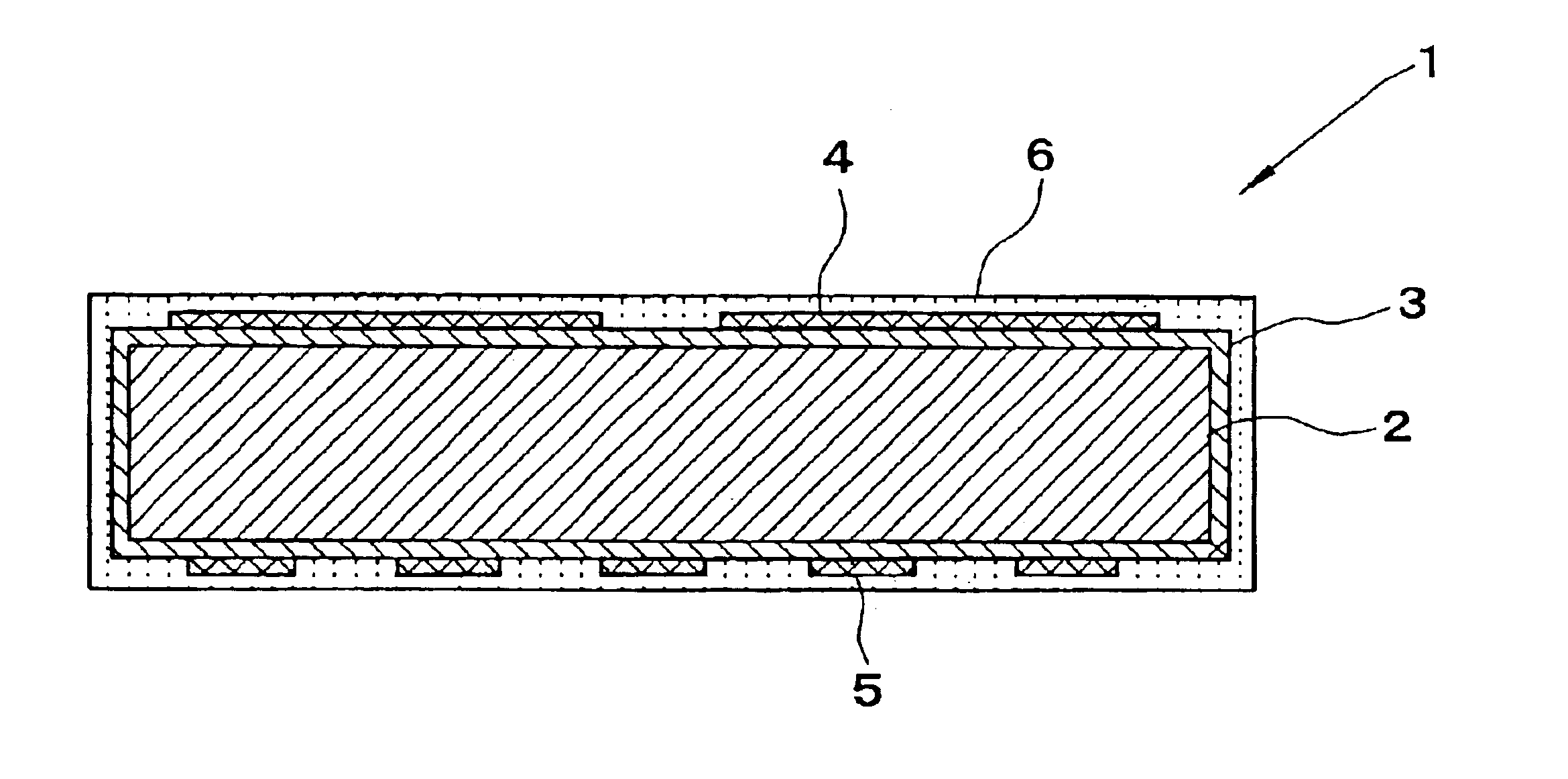
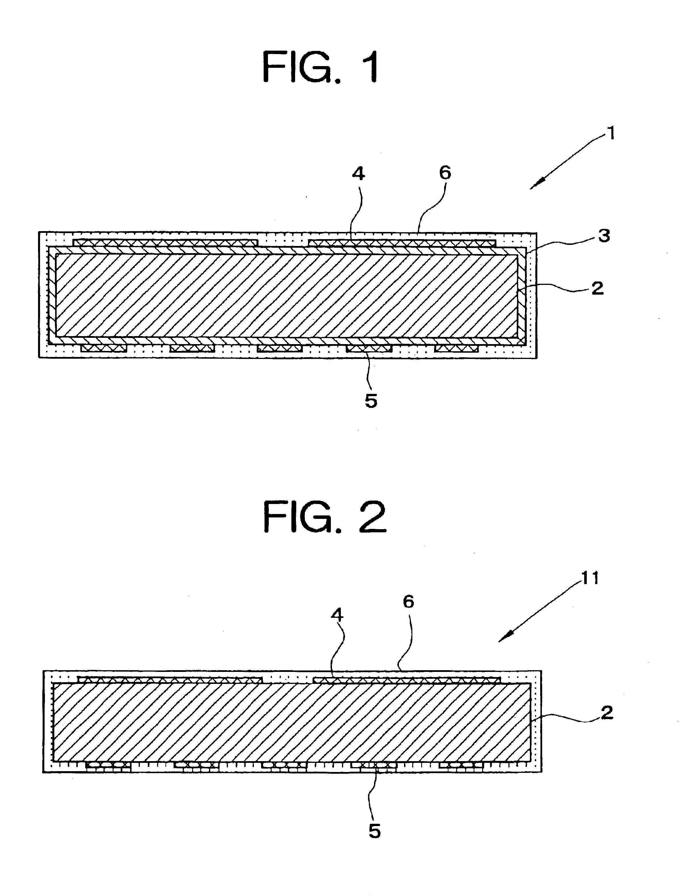
[0056]A graphite base having a diameter of 200 mm and a thickness of 15 mm was prepared, and reaction of ammonia with boron trichloride was performed in a reaction chamber under the condition of 1800° C. and 100 Torr to form a protective layer composed of pyrolytic boron nitride on the base. Subsequently, on the protective layer, methane gas was pyrolyzed under the condition of 2200° C. and 5 Torr, and boron halide was introduced into the same reaction chamber in the range of 0.001-30% by weight as a boron concentration to form a pyrolytic graphite layer which has a thickness of 100 μm and in which boron and boron carbide were mixed. The front side of this pyrolytic graphite layer was processed into an electrode pattern to form electrode for electrostatic attraction, and the back side thereof was processed into a heater pattern to form heating layer. Moreover, on both surfaces thereof, reaction of ammonia, boron trichloride and methane was performed under the condition of 1600° C. a...


PUM

PropertyMeasurementUnit
Temperatureaaaaaaaaaa
Percent by massaaaaaaaaaa
Electrical resistivityaaaaaaaaaa

Abstract

There is disclosed a heating apparatus with electrostatic attraction function 1, comprising at least a supporting base 2, an electrode for electrostatic attraction 4 and a heating layer 5 that are formed on the supporting base, and an insulating layer 6 that is formed on the electrode for electrostatic attraction and the heating layer, wherein the electrode for electrostatic attraction and / or the heating layer are / is composed of pyrolytic graphite containing boron and / or boron carbide of 0.001-30% by weight in terms of boron concentration, and the insulating layer has an electric resistivity of 106-1015 Ωcm. There is provided a heating apparatus with electrostatic attraction function, which has a high thermal shock resistance, no problem of delamination, a proper resistance value, and a sufficient electrostatic attraction force even in a medium and high temperature range of 500-800° C., which causes no breakage of devices due to leakage current, and which can be used stably during rapid rise and rapid drop in temperature.

Description

BACKGROUND OF THE INVENTION[0001]1. Field of the Invention[0002]The present invention relates to a heating apparatus with electrostatic attraction function, and more particularly to a wafer heating apparatus with electrostatic attraction function, which is preferably used for a heating process of a semiconductor wafer during a fabrication process of semiconductor devices including a temperature rising process.[0003]2. Description of the Related Art[0004]For heating a semiconductor wafer during a fabrication process of semiconductor devices, a heater in which a metal-wire is wound was used conventionally. However, since there was a problem of metal contamination to a semiconductor wafer when this heater was used, in recent years there has been proposed using a wafer heating apparatus united with ceramics in which a ceramics thin film is used as a heating layer (for example, see Japanese Patent Laid-Open (Kokai) No. 4-124076).[0005]Also, in the case of heating a semiconductor wafer, a...

Claims


Application Information

Patent Timeline
IPC IPC(8): H01L21/00H01L21/683H01L21/67C04B35/52H05B3/20H01L21/02H05B3/10H05B3/14H05B3/74
CPCH01L21/67103H01L21/6831H05B3/143H01L21/02
Inventor KANO, SHOJIIWAI, RYOUJIARAI, NOBUO
Owner SHIN ETSU CHEM IND CO LTD
Learn More