
Prism construction for simultaneous zero-degree and oblique illumination of a stereoscopic surgical microscope

a stereoscopic and surgical microscope technology, applied in the field of prism construction, can solve problems such as retinal light spots, and achieve the effect of effective eye protection and effective eye protection

Inactive Publication Date: 2005-07-05
LEICA INSTR SINGAPORE PTE
View PDF15 Cites 12 Cited by
  • Summary
  • Abstract
  • Description
  • Claims
  • Application Information

AI Technical Summary

Benefits of technology

[0012]The objects of the invention are thus to create an illumination apparatus which optimally utilizes the light inlet pupil and, when the red-reflection illumination of the ocular fundus is no longer needed, makes possible effective eye protection for the patient without reducing the intensity of the specimen field illumination, thus eliminating the disadvantages of the existing art mentioned initially. The sequence of the two objects can also be reversed, namely that an effective eye protection is made possible, and moreover the light inlet pupil is optimally utilized.
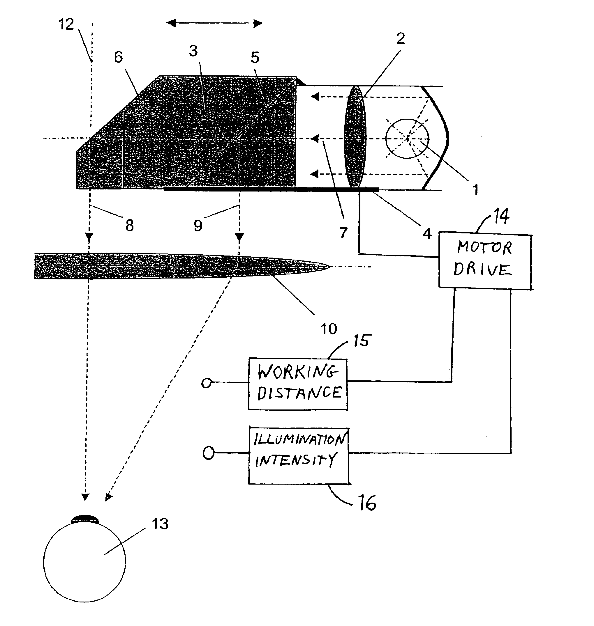
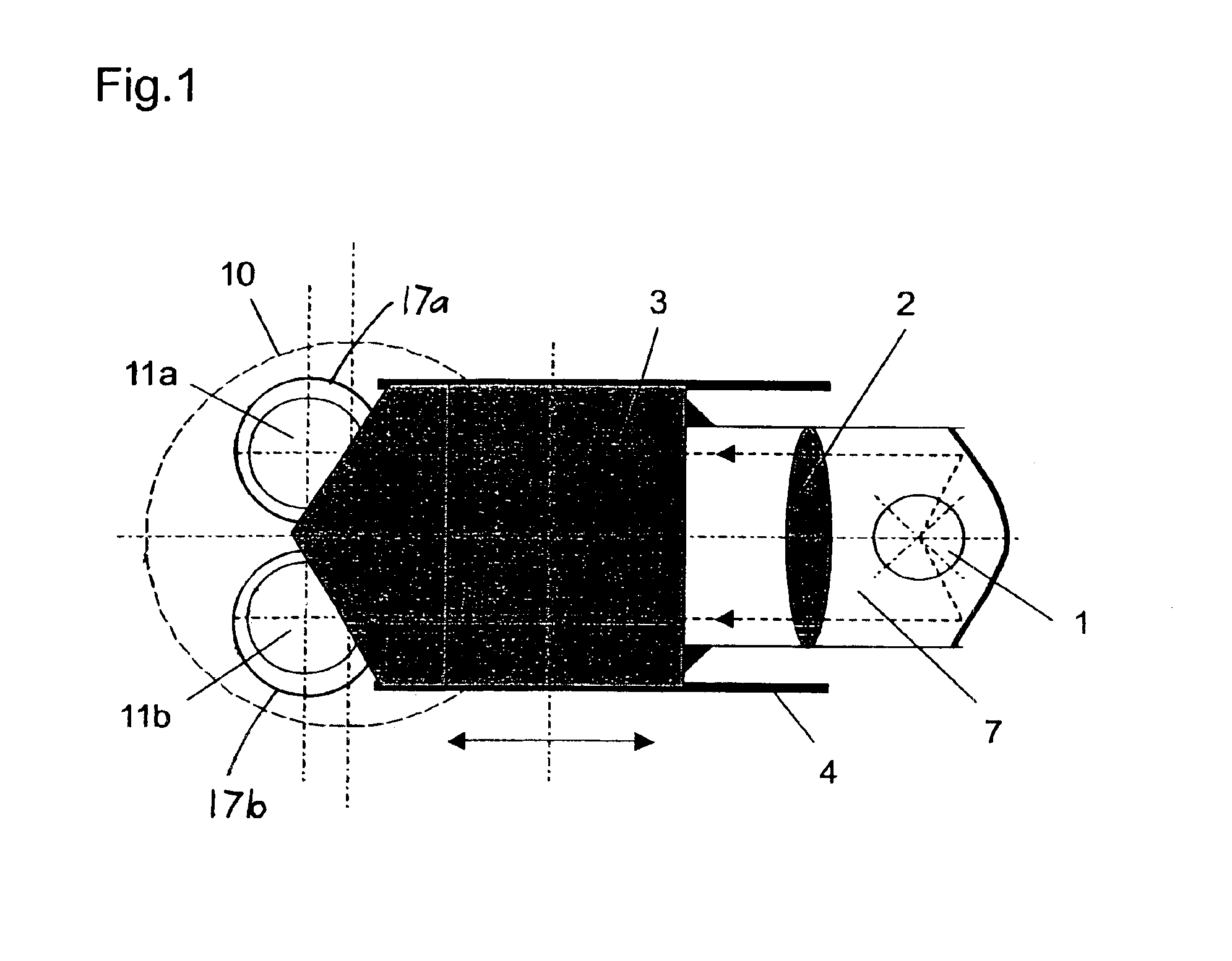
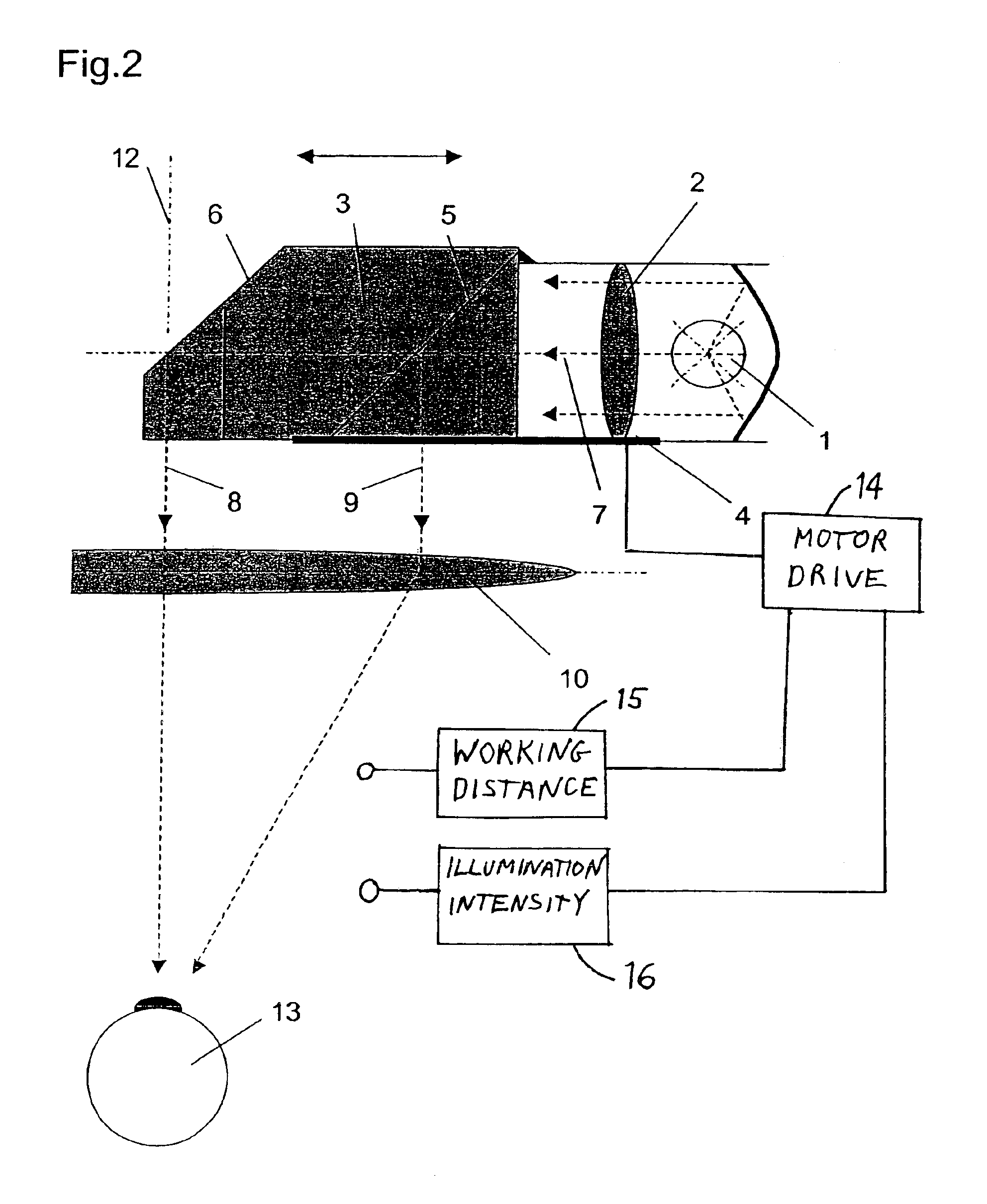
[0014]The deflection element is embodied as a prism combination for deflecting a first illumination sub-beam a long distance from the optical axis of the main objective (oblique illumination) and for deflecting a second illumination sub-beam a short distance from the optical axis of the main objective (implementation of zero-degree illumination). The deflection element accepts light from the entire illumination pupil, and thus covers the entire area of the first deflection element (6 degrees). A very low overall height is also thereby obtained.
[0015]Protection for the patient's eye is provided by the fact that the prism combination with the downstream illuminating optical system is shifted away from the observation beam paths. The result of this is that the light spot which occurs on the retina, and can be harmful in the vicinity of the macula, is also moved away from that location. The surgeon shifts the entire illumination unit when he or she no longer needs the red reflection; the same specimen field illumination is then nevertheless still available, but now without the red reflection, and merely at a different angle. This shift can be actuated, according to the present invention, in manual or motorized fashion. The eye protection can, of course, also be combined with a different construction for reflecting in light (omitting the prism combination), and conversely the prism combination according to the present invention can also advantageously be used independently of the shifting capability.

Problems solved by technology

The result of this is that the light spot which occurs on the retina, and can be harmful in the vicinity of the macula, is also moved away from that location.

Method used


Image

  • Prism construction for simultaneous zero-degree and oblique illumination of a stereoscopic surgical microscope
  • Prism construction for simultaneous zero-degree and oblique illumination of a stereoscopic surgical microscope
  • Prism construction for simultaneous zero-degree and oblique illumination of a stereoscopic surgical microscope

Examples


Embodiment Construction

[0023]FIG. 1 schematically depicts, in plan view, a system for reflecting in illumination having a light source 1, an illuminating optical system 2, a prism combination 3 immovably joined to light source 1 and illuminating optical system 2, and having a shifting apparatus 4 for prism combination 3, an illumination beam 7, a main objective 10, observation beam paths 11a, 11b, and lens tubes 17a, 17b respectively associated with observation beam paths 11a, 11b.

[0024]FIG. 2 schematically shows the system for reflecting in illumination depicted in FIG. 1, as a sectioned image seen from the side, having: a light source 1; an illuminating optical system 2; a prism combination 3, with a beam splitter surface 5 and a totally reflective mirror surface 6, that is located centeredly with respect to optical axis 12 of the main objective; an illumination sub-beam 8 for zero-degree illumination of specimen 13; an illumination sub-beam 9 that deviates from optical axis 12 of the main objective; a...


PUM


Abstract

The invention concerns an apparatus for simultaneous zero-degree and oblique illumination for an optical viewing device, in particular a stereoscopic surgical microscope, which contains a shiftable prism combination (3) for deflecting a first illumination sub-beam a long distance from the optical axis (12) of the main objective in order to obtain an oblique illumination beam (9) (oblique illumination), and for deflecting a second illumination sub-beam (8) a short distance from the optical axis (12) of the main objective in order to obtain a zero-degree illumination (8).

Description

CROSS REFERENCE TO RELATED APPLICATIONS[0001]This application claims priority of the German patent application 101 44 067.7 filed Sep. 7, 2001 which is incorporated by reference herein.FIELD OF THE INVENTION[0002]The invention concerns a prism construction for simultaneous zero-degree and oblique illumination of a stereoscopic surgical microscope.BACKGROUND OF THE INVENTION[0003]Stereoscopic surgical microscopes often possess a system for reflecting in illumination with which an illumination beam path is split by way of a deflection device into an oblique and a zero-degree partial beam, which are switched into the main beam path of the microscope.[0004]Reflected-in beam paths for illumination of a specimen field are used in a wide variety of applications, in particular including ophthalmology. In this context, the patient's eye is usually illuminated directly by the surgical microscope's illumination. If the brightness is excessive, this greatly endangers the retina in particular bu...

Claims


Application Information

Patent Timeline
IPC IPC(8): G02B21/00G02B21/18G02B21/22A61B3/13A61B19/00A61B90/20G02B21/06A61B90/30A61F9/007G02B21/08
CPCG02B21/0012G02B21/22A61B3/132A61B19/5202A61B19/5223A61B90/30A61B90/20
Inventor DEVERIN, JACQUES ALAINSANDER, ULRICH
Owner LEICA INSTR SINGAPORE PTE
Learn More