
Method for controlling deployment of an occupant protection device

a technology for protecting devices and occupants, applied in child seats, instruments, tractors, etc., can solve problems such as errors in all predictive devices, delayed deployment of airbags, and serious injuries to occupants, and achieve accurate discrimination and more of the image of occupants

Inactive Publication Date: 2005-06-28
AMERICAN VEHICULAR SCI
View PDF90 Cites 17 Cited by
  • Summary
  • Abstract
  • Description
  • Claims
  • Application Information

AI Technical Summary

Benefits of technology

[0025]The occupant position sensor of this invention is adapted for installation in the passenger compartment of an automotive vehicle equipped with a passenger passive protective device (also referred to herein as an occupant restraint device) such as an inflatable airbag. When the vehicle is subjected to a crash of sufficient magnitude as to require deployment of the passive protective device (airbag), and the crash sensor system has determined that the device is to be deployed, the occupant position sensor and associated electronic circuitry determines the position of the vehicle occupant relative to the a bag and the velocity of the occupant and disables deployment of the airbag if the occupant is positioned and / or will be positioned so that he / she is likely to be injured by the deploying airbag.
[0027]The placement of the position (and velocity) sensor on the steering wheel or its assembly or on the airbag module provides an extremely precise and direct measurement of the distance between the occupant and the airbag (assuming the airbag is arranged in connection with the steering wheel). Obviously, this positioning of the sensor is for use with a driver airbag. For the passenger, the placement of the position (and velocity) sensor on or adjacent and in connection with the airbag module provides a similarly extremely precise and direct measurement of the distance between the passenger and the airbag.
[0029]It is a principal object of this invention to provide an occupant position and velocity sensor which reliably permits, and in a timely manner, a determination to be made that he / she is out of position, or will become out of position, and likely to be injured by a deploying airbag.
[0033]It is also a principal object of this invention to provide a system which could accurately discriminate between the occupant's head or chest and other parts of the body in determining the occupant's position and velocity.
[0034]It is another object of this invention to independently prevent the deployment of the driver or passenger airbags if either occupant is out of position.
[0035]It is still another object of this invention to provide for a more complete analysis of an occupant through the use of receiver arrays, e.g., CCD's or CMOS arrays, to capture more of the occupant's image.

Problems solved by technology

Regardless of where sensors are mounted there will always be crashes where the sensor triggers late and the occupant has moved to a position near to the airbag deployment cover.
In such cases, the occupant may be seriously injured or even killed by the deployment of the airbag.
In such cases, even at moderate velocity changes where an airbag might be of help in mitigating injuries, the crush zone mounted sensor might not actually be in the crush zone at the time that sensor triggering is required for timely airbag deployment, and as a result can trigger late when the occupant is already resting against the airbag module.
Thus, sensors mounted in the passenger compartment or other non-crush zone locations, will also trigger the deployment of the airbag late on many crashes.
All predictive devices are subject to error, so that sometimes the airbag will be inflated when it is not needed and at other times it will not be inflated when it could have prevented injury.
The 50% male, however, is actually the 70% person and therefore about 70% of the population sit on average closer to the airbag than the 50% male and thus are exposed to a greater risk of interacting with the deploying airbag.
A single sensor triggering time criterion that fails to take this into account, therefore, will cause injuries to small people or deny the protection of the airbag to larger people.
A further complication results from the fact that a greater number of occupants are now wearing seatbelts which tends to prevent many of these occupants from getting too close to the airbag.
Thus, just knowing the initial position of the occupant is insufficient and either the position must be continuously monitored or the seatbelt use must be known.
Also, the occupant may have fallen asleep or be unconscious prior to the crash and be resting against the steering wheel.
This calculation can be greatly in error for the different seating positions discussed above and also for the seatbelted occupant, and thus an occupant who wears a seatbelt could be denied the added protection of the airbag in a severe crash.
As the number of vehicles which are equipped with airbags is now rapidly increasing, the incidence of late deployments is also increasing.
There are also now many known fatalities where a late airbag deployment is suspected as the cause.
Each of these systems, however, has significant limitations.
Sensors of this type can be used to accurately obtain the initial position of the occupant but the determination of the occupant's velocity, and thus the prediction of when he / she is likely to be too close to the deploying airbag, will necessarily be inaccurate due to the long delay between position points and thus the small number of such points available for the prediction and the inherent noise in the reflected signal.
The object of an occupant position sensor is to determine the location of the head and / or chest of the vehicle occupant relative to the airbag since it is the impact of either the head or chest with the deploying airbag which can result in serious injuries.
Both such mounting locations are particularly prone to detection errors due to positioning of the occupant's hands, arms and legs.
Mattes et al. further describe the placement of the sensor in the headrest but such an arrangement is insufficient since it measures the distance from the headrest to the occupant and not from the airbag.
Such a combination, however, would not differentiate between an occupant with both hands and arms in the path of the ultrasonic transmitter at such a location that it was blocking a substantial view of the occupant's head or chest.
Since the sizes and driving positions of occupants are extremely varied, pattern recognition systems are required when a clear view of the occupant, unimpeded by his / her extremities, newspapers, etc., cannot be guaranteed.

Method used


Image

  • Method for controlling deployment of an occupant protection device
  • Method for controlling deployment of an occupant protection device
  • Method for controlling deployment of an occupant protection device

Examples


Embodiment Construction

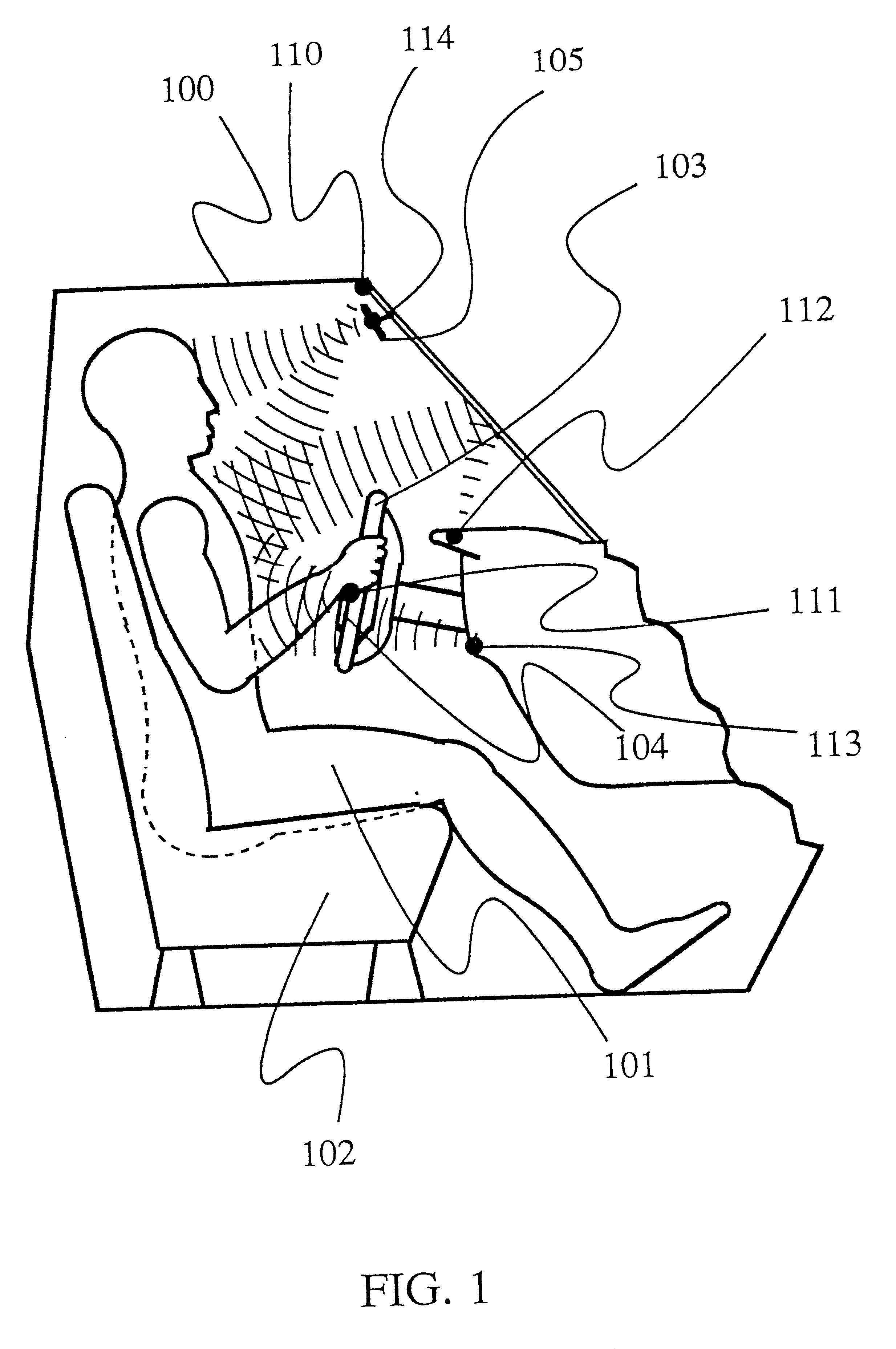
[0056]Referring now to the drawings wherein the same reference numerals refer to the same or similar elements, a section of the passenger compartment of an automobile is shown generally as 100 in FIG. 1. A driver of a vehicle 101 sits on a seat 102 behind a steering wheel 103 which contains an airbag assembly 104. Five transmitter and / or receiver assemblies 110, 111, 112, 113 and 114 are positioned at various places in the passenger compartment to determine the position of the occupant (driver in this case) relative to the airbag, i.e., the location of one or more parts of the driver, such as the head, chest and torso of the driver, relative to the airbag. Usually, in any given implementation, three or four of the transmitters and receivers would be used depending on their mounting locations as described below.

[0057]FIG. 1 illustrates several of the possible locations of such devices. For example, transmitter and receiver 110 emits ultrasonic acoustical waves which bounce off the ch...


PUM


Abstract

Method for controlling a vehicular component based on the position and velocity of an occupant in which the current position and velocity of the occupant are determined, an expected position of the occupant is determined based on the current position and current velocity of the occupant and the component is controlled in consideration of the expected position of the occupant. If the component is a deployable occupant protection device, deployment can be suppressed if the expected position of the occupant is not in a predetermined acceptable position for deployment of the occupant protection device, i.e., the occupant is out-of-position. The position and velocity can be determined several times after the start of the crash and prior to deployment of the occupant protection device so as to enable continual adjustment and control thereof based on the most recent position and velocity of the occupant. The position and velocity of the occupant can be determined using a wave transmitter / receiver arrangement. The velocity of the occupant can be determined from successive position measurements.

Description

CROSS REFERENCE TO RELATED APPLICATIONS[0001]This application is a continuation-in-part of U.S. patent application Ser. No. 08 / 905,877 filed Aug. 4, 1997 , now U.S. Pat. No. 6,186,537, which in turn is a continuation of U.S. patent application Ser. No. 08 / 505,036 filed Jul. 25, 1995, now U.S. Pat. No. 5,653,462, which in turn is a continuation of U.S. patent application Ser. No. 08 / 040,978 filed Mar. 31, 1993, now abandoned, which in turn is a continuation-in-part of U.S. patent application Ser. No. 07 / 878,571 filed May 5, 1992, now abandoned.[0002]This application is also a continuation-in-part application of U.S. patent application Ser. No. 09 / 409,625 filed Oct. 1, 1999, now U.S. Pat. No. 6,270,116, U.S. patent application Ser. No. 09 / 448,337 filed Nov. 23, 1999, now U.S. Pat. No. 6,283,503, and U.S. patent application Ser. No. 09 / 448,338 filed Nov. 23, 1999, now U.S. Pat. No. 6,283,503, all of which are also continuation-in-part applications of the '877 application.FIELD OF THE I...

Claims


Application Information

Patent Timeline
IPC IPC(8): B60N2/00B60N2/26B60N2/02B60N2/48B60R22/18B60R21/01B60R22/20B60N2/28B60R16/02B60R1/08G01S17/88G01S15/88G01S15/00G01S15/87G01S7/02G01S17/00G01S7/48G01S7/41G01S7/539G06K9/00B60R22/00B60R21/20B60R22/48B60R21/26B60R1/12G01S13/00G01S13/04G01S15/06G01S17/89B60R16/037B60R21/0132B60R21/015B60R21/2165B60R21/276
CPCB60N2/002B60N2/0248B60N2/0276B60N2/28B60N2/2806B60N2/2863B60N2/4829B60N2/4852B60N2/4885B60R1/088B60R16/037B60R22/20B60R25/25G01S7/417G01S7/4802G01S7/539G01S15/87G01S15/88G01S17/88G06K9/00362B60R21/01554B60R21/01536B60R21/01516B60R21/01534B60R21/01538B60R21/01542B60R21/01552B60N2/0232B60R21/01544B60N2002/0268B60R21/0132B60R21/21656B60R21/276B60R2001/1223B60R2001/1253B60R2021/0027B60R2021/26094B60R2021/2765B60R2022/4825G01S13/04G01S15/06G01S17/89B60R21/01548B60N2/888B60N2/829B60N2/853G06V40/10B60N2/0268B60N2/02246B60N2220/20B60N2230/30B60N2220/10B60N2210/24B60N2/0022B60N2/0029B60N2/0035B60N2/0028B60N2210/12B60N2210/18B60N2210/26B60R21/015
Inventor BREED, DAVID S.JOHNSON, WENDELL C.DUVALL, WILBUR E.
Owner AMERICAN VEHICULAR SCI
Learn More