
Combined sensor and heating element

Inactive Publication Date: 2005-06-14
IEE INT ELECTRONICS & ENG SA
View PDF9 Cites 51 Cited by
  • Summary
  • Abstract
  • Description
  • Claims
  • Application Information

AI Technical Summary

Benefits of technology

[0007]According to the invention, this object is achieved by a combined sensor and heating element with a sensor mat having a plurality of active regions interconnected by flexible connection strips and by a heat conductor, the heat conductor being directly applied to the flexible connection strips of the sensor mat. With this sensor and heating element, the heat conductor therefore does not have to be embedded separately into a handy nonwoven laminate which is subsequently fixed to the sensor mat. The manufacture of such a combined sensor and heating element therefore requires essentially less individual steps than the manufacture of conventional combined elements. Moreover, less material is needed for the manufacture of the function element according to the invention than with conventional function elements. The combined sensor and heating element of the present invention therefore represents a particularly simple and inexpensive combined element.
[0012]In a particularly advantageous embodiment, the heat conductor comprises a high-resistivity material with a positive temperature coefficient. Such high-resistivity materials comprise a higher electric resistance with high temperatures than with low temperatures. With a proper material selection, this effect can be utilized for limiting the heat current, so that a complex downstream temperature control for the heating element can be omitted.
[0013]The electric connections of the sensor mat and the electric connections of the heat conductor are preferably arranged at a common terminal lug of the combined sensor and heating element. Thereby, a contacting of the two separate functions by a single plug element is allowed and the subsequent assembly is thus essentially facilitated. In a possible embodiment, the two separate function elements can, for example, be connected to a common electronic system. This electronic system then serves for evaluating the sensor mat as well as for supplying the heating mat and controlling the performance thereof. An intelligent control can, for example, prevent the seat heater from being switched on if the corresponding seat is not occupied.

Problems solved by technology

The manufacture of such a combined sensor and heating element, however, is relatively time consuming and expensive as the two function elements first have to be manufactured separately and then have to be fixed to one another.

Method used


Image

  • Combined sensor and heating element
  • Combined sensor and heating element
  • Combined sensor and heating element

Examples


Embodiment Construction

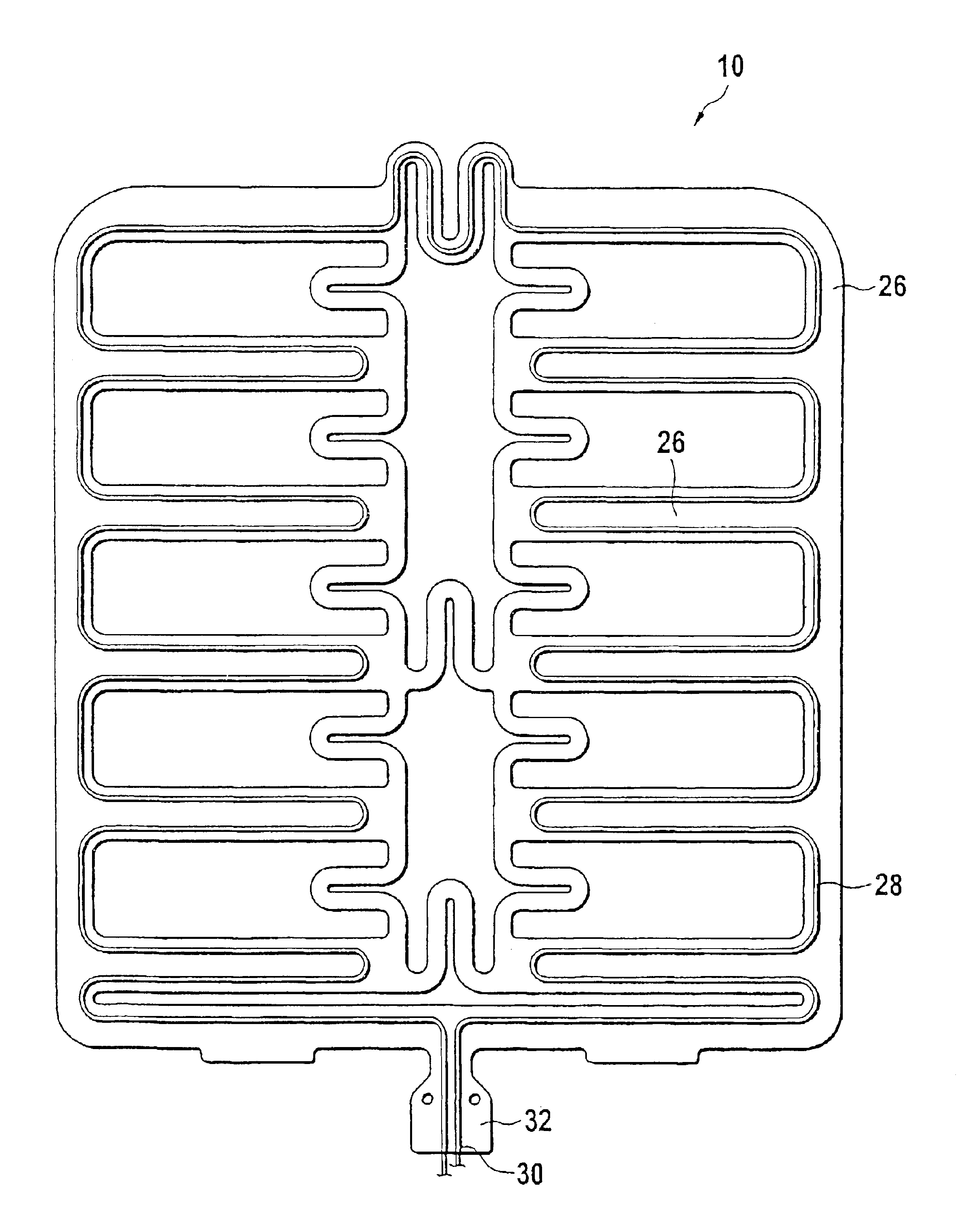
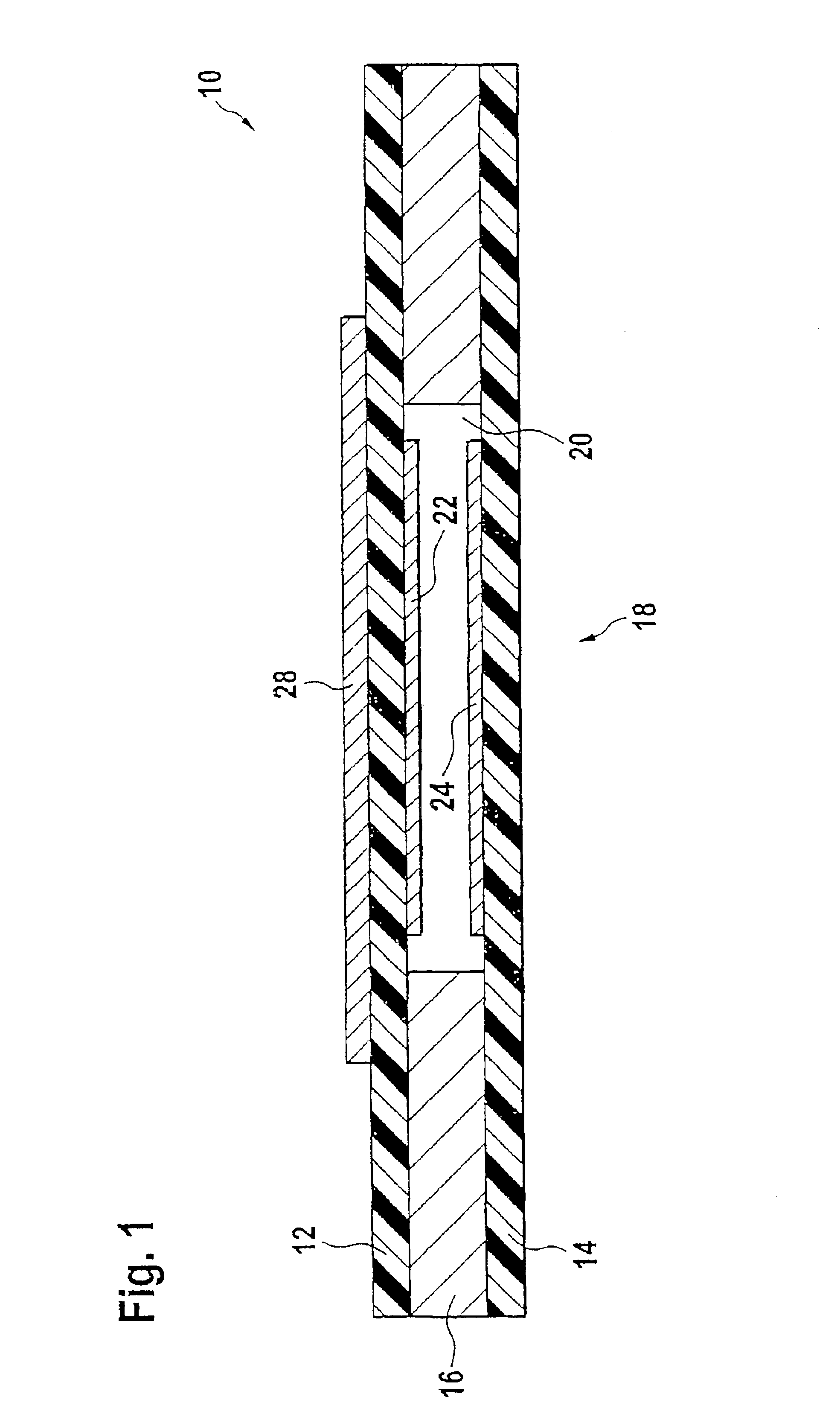
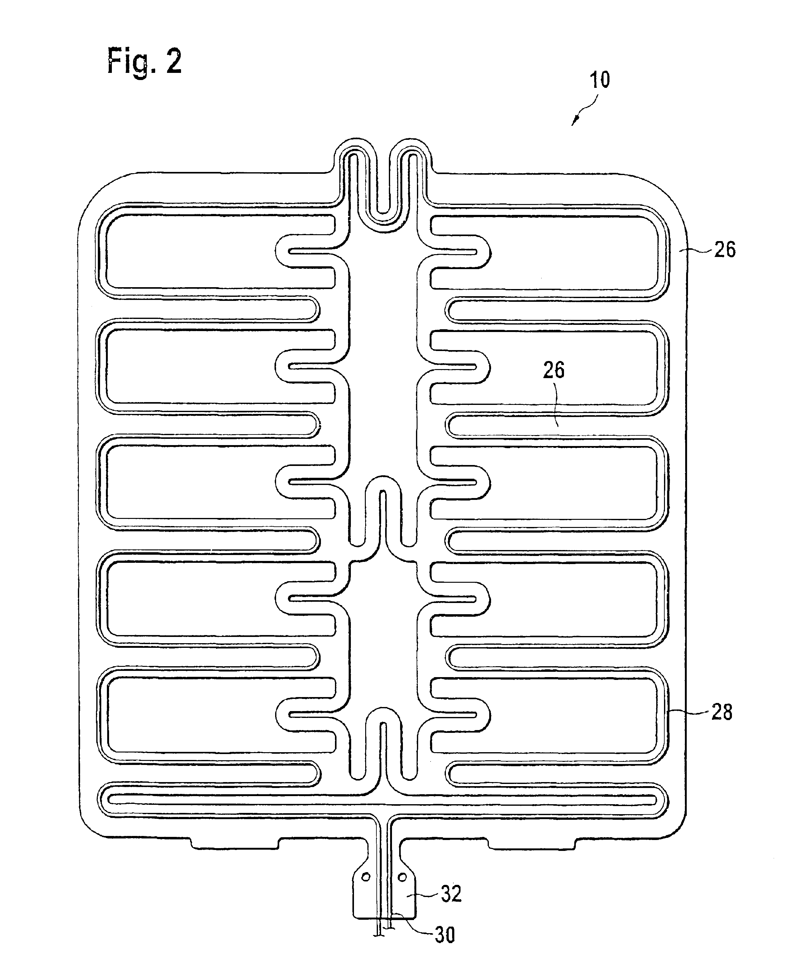
[0018]Seat occupancy sensors or sensors for receiving or evaluating a seating profile are often designed as pressure-sensitive foil-style sheet sensors. Such a seat occupancy sensor in general comprises a plurality of active regions distributed across a certain area and interconnected by flexible connection lines of the sensor. Such a sensor is represented in FIGS. 1 and 2, FIG. 1 representing a section through an active region of the sensor.

[0019]The sensor comprises a first and a second carrier foil 12 and 14 laminated together by means of a spacer 16, for example a double-sided bonding sheet. In the region of the active regions 18 of the sensor 10, the spacer 16 comprises a recess 20, so that in this region the two carrier foils 12 and 14 are opposed in a spaced manner.

[0020]In the active region 18 of the sensor, contact arrays 22 and 24 are arranged at the inside of the carrier foils 12 and 14 between which an electric contact is created when the two carrier foils are compressed...


PUM


Abstract

A combined sensor arid heating element includes a sensor mat having several active regions interconnected by flexible connection strips. The flexible connection strips each include two carrier foils laminated together having contact arrangements arranged in the active regions at the inside of the carrier foils. Each flexible connection strips further include a heat conductor directly applied to an outer side of one of the carrier foils.

Description

CROSS-REFERENCE TO RELATED APPLICATIONS[0001]This application is entitled to the benefit of International Application No. PCT / EP01 / 04549 filed on Apr. 23, 2001 and Luxembourg Patent Application No. 90583 filed on May 17, 2000.FIELD OF THE INVENTION[0002]The present invention relates to a combined sensor and heating element, in particular to be employed in a vehicle seat.BACKGROUND OF THE INVENTION[0003]Modern vehicles are increasingly often equipped e.g. with so-called seat occupancy sensors which, in case of an accident, prevent the release of an airbag attributed to a certain vehicle seat if the corresponding vehicle seat is not occupied. Such seat occupancy sensors frequently comprise a sensor mat with a plurality of pressure-sensitive regions which are interconnected by flexible connection strips. The sensor mat is integrated into the vehicle seat such that the pressure-sensitive regions are distributed across the seat squab of the vehicle seat.[0004]The increased consumer's dem...

Claims


Application Information

Patent Timeline
IPC IPC(8): B60N2/00B60N2/56B60R21/01H05B3/34A47C7/74G01L5/00A47C27/00B60R21/015H05B3/00H05B3/20
CPCB60N2/002B60N2/5685H05B3/34B60R21/0154G01G19/4142B60R21/01516H05B2203/029H05B2203/013
Inventor SCHMIZ, MARCSCHOCKMEL, PAUL
Owner IEE INT ELECTRONICS & ENG SA
Learn More