
Fixation device for a portable orbital drilling unit

a technology of fixing device and orbital drilling unit, which is applied in the direction of boring/drilling components, profiling/shaping machines, and process control systems, etc. it can solve the problems of not meeting the requirements of cutting tool geometry, and affecting the machining operation of the machin

Inactive Publication Date: 2005-06-07
NOVATOR
View PDF28 Cites 13 Cited by
  • Summary
  • Abstract
  • Description
  • Claims
  • Application Information

AI Technical Summary

Benefits of technology

[0014]An advantage of the present invention is that the fixation device maintains the orientation of a rotating machine tool with respect to the workpiece during the machining process.
[0015]Another advantage of the present invention is that the fixation device is easily released from the template.
[0016]Yet another advantage of the present invention is the ability of the fixation device to remove and exhaust machining debris from the machining area during the machining process.

Problems solved by technology

The use of a template with a portable or hand tool can be problematic due to the inherent positioning flexibility and degrees of freedom of motion of the tool which now must be constrained to follow the template pattern.
The requirements imposed on the geometry of the cutting tool are not particularly high, on the other hand, since every individual tool is simply calibrated before use.
A hand tool apparatus as disclosed in U.S. Pat. No. 6,382,890 (Linderholm) has advantages over a fixed machine tool in terms of flexibility and more degrees of freedom in motion and positioning; however, these same advantages can create difficulty in maintaining the proper orientation of the hand tool apparatus with respect to the template and workpiece during the machining operation.
This difficulty may be particularly evident during an orbital drilling process when the tool is subjected to both an axial force and a radial force through the cutting tool tip by virtue of machining simultaneously in both an axial and radial direction.

Method used


Image

  • Fixation device for a portable orbital drilling unit
  • Fixation device for a portable orbital drilling unit
  • Fixation device for a portable orbital drilling unit

Examples


Embodiment Construction

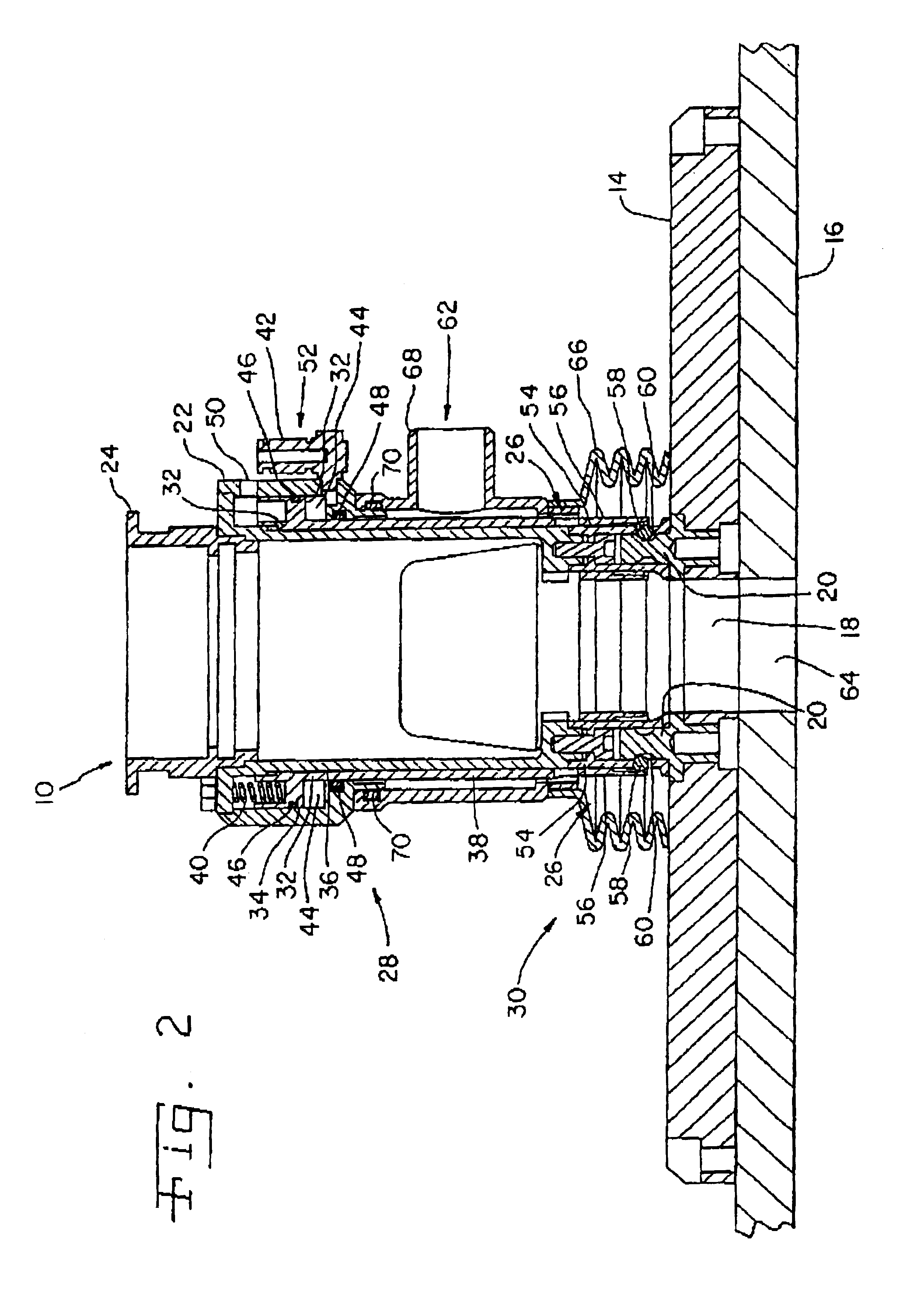
[0021]Referring now to the drawings, and more particularly to FIG. 1, there is shown a fixation device 10 of the present invention with a rotating machine tool 12 mounted on and therein and shown clamped to a machining template 14 with workpiece 16.

[0022]Workpiece 16 may be made of a composite material, such as a fiber-reinforced composite material, or alternatively, may be of metal composition including alloys or a combined metal and composite makeup. Workpiece 16 may be flat or have curved surfaces or other surface geometries. Machining area 64 in workpiece 16 may be a hole or other geometries as dictated by workpiece 16 form, fit, function and / or design.

[0023]Rotating machine tool 12 is shown as a portable orbital drilling unit; alternatively, rotating machine tool 12 can be a grinding tool, a milling tool or a boring tool.

[0024]Template 14 includes at least one hole 18 and at least one locating pin 20. Hole 18 may be circular or other geometries as required by workpiece 16 machi...


PUM


Abstract

A fixation device for positioning a rotating machine tool onto a template, the template having at least one hole and at least one locating pin. The fixation device includes a housing with a housing tool end and a housing template end, a seat located on the housing tool end for coupling with the rotating machine tool, and a clamping mechanism disposed at least partially at the housing template end for coupling with at least one locating pin.

Description

CROSS REFERENCE TO RELATED APPLICATIONS[0001]This is a non-provisional application which claims priority under 35 U.S.C. § 120 U.S. provisional patent application Ser. No. 60 / 299,007, entitled “FIXATION DEVICE FOR A PORTABLE ORBITAL DRILLING UNIT”, filed Jun. 18, 2001.BACKGROUND OF THE INVENTION[0002]1. Field of the Invention[0003]The present invention relates to a fixation device for mounting a hand tool to a drill template when cutting a hole in an object, and, more particularly, a fixation device used with a drill template and a hand tool for cutting a hole that has a larger diameter than the diameter of the cutting tool.[0004]2. Description of the Related Art[0005]When machining materials using a portable or hand tool, many advantages are achieved due to the flexible positioning of the tool and degrees of freedom of motion of the tool with respect to the workpiece. The advantages of using a portable or hand tool include the ability to position the tool in positions not allowed b...

Claims


Application Information

Patent Timeline
IPC IPC(8): B23Q16/00B23Q11/00B23Q16/02B23Q35/00B23B49/00B23B49/02B23B45/14
CPCB23B49/02B23Q11/0046B23Q16/021B23Q35/00Y10T409/306384Y10T409/307616Y10T409/303808Y10T409/303696Y10T409/304424Y10T409/307112Y10T82/125Y10T408/56253Y10T408/56245
Inventor PETTERSSON, BJORNWIKLUND, MARCUS
Owner NOVATOR
Learn More