
Material system for Bragg reflectors in long wavelength VCSELs

a material system and bragg reflector technology, applied in the field of laser mirrors, can solve the problems of difficult to produce high-quality alas/gaas dbr on inp substrates, prior art distributed bragg reflectors (dbr) significantly less than optimal, and achieve good thermal conductivity and high index of refraction differences

Inactive Publication Date: 2005-05-31
II VI DELAWARE INC
View PDF9 Cites 2 Cited by
  • Summary
  • Abstract
  • Description
  • Claims
  • Application Information

AI Technical Summary

Benefits of technology

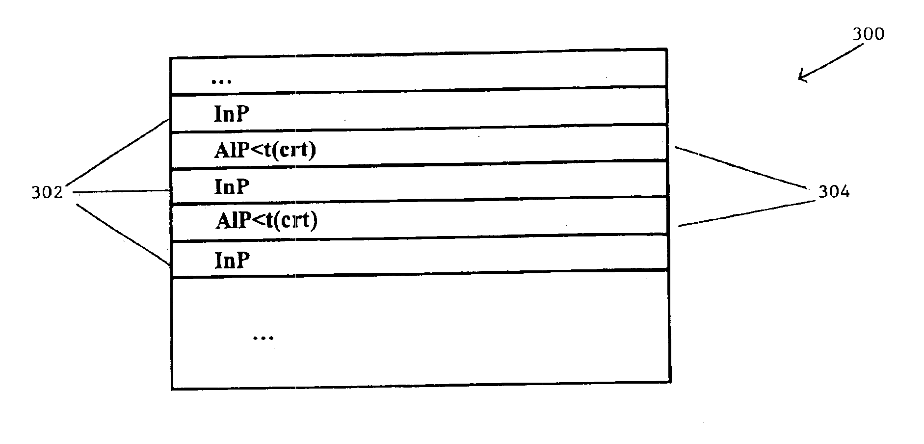
The present invention is about a new type of distributed Bragg reflector (DBR) mirror binary material system (AlP) that has good thermal conductivity. This material can be fabricated on an InP substrate without changing the group V material (P). The DBR is made up of layers of aluminum (Al) and potassium aluminum phosphate (AlP). When grown on an InP substrate, an AlP DBR can have two different forms, depending on the critical layer thickness of AlP. If the critical layer thickness is greater than λ / 4nAlP, an alternating layer of InP and AlP can be used. However, if the critical layer thickness is less than λ / 4nAlP, an alternating layer of InP and an AlP / InP superlattice can be used. This new material system can be used in vertical cavity surface emitting lasers (VCSELs) to improve their performance.

Problems solved by technology

While generally successful, VCSELs have problems.
In particular, in some applications the prior art distributed Bragg Reflectors (DBR) are significantly less than optimal.
Unfortunately, because of the high degree of lattice mismatch between AlAs / GaAs and InP, it is very difficult to produce a high quality AlAs / GaAs DBR on an InP substrate.
Unfortunately, material systems comprised of more than two materials tend to have low thermal conductivity, which makes heat difficult to remove, and low refractive index differences, which means that many stacked layers are required.
This increases fabrication costs and time.

Method used


Image

  • Material system for Bragg reflectors in long wavelength VCSELs
  • Material system for Bragg reflectors in long wavelength VCSELs
  • Material system for Bragg reflectors in long wavelength VCSELs

Examples


Embodiment Construction

[0032]The principles of the present invention provide for DBRs comprised of stacked layers of Al and of P. Those stacked layers are beneficially fabricated on an InP substrate, and can be done so without changing the group V material (P). Furthermore, a combination of an InP substrate and an AlP DBR are particularly useful in long-wavelength VCSEL applications.

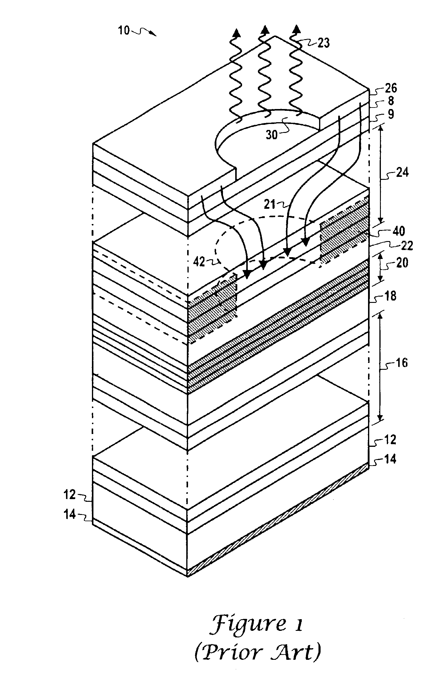
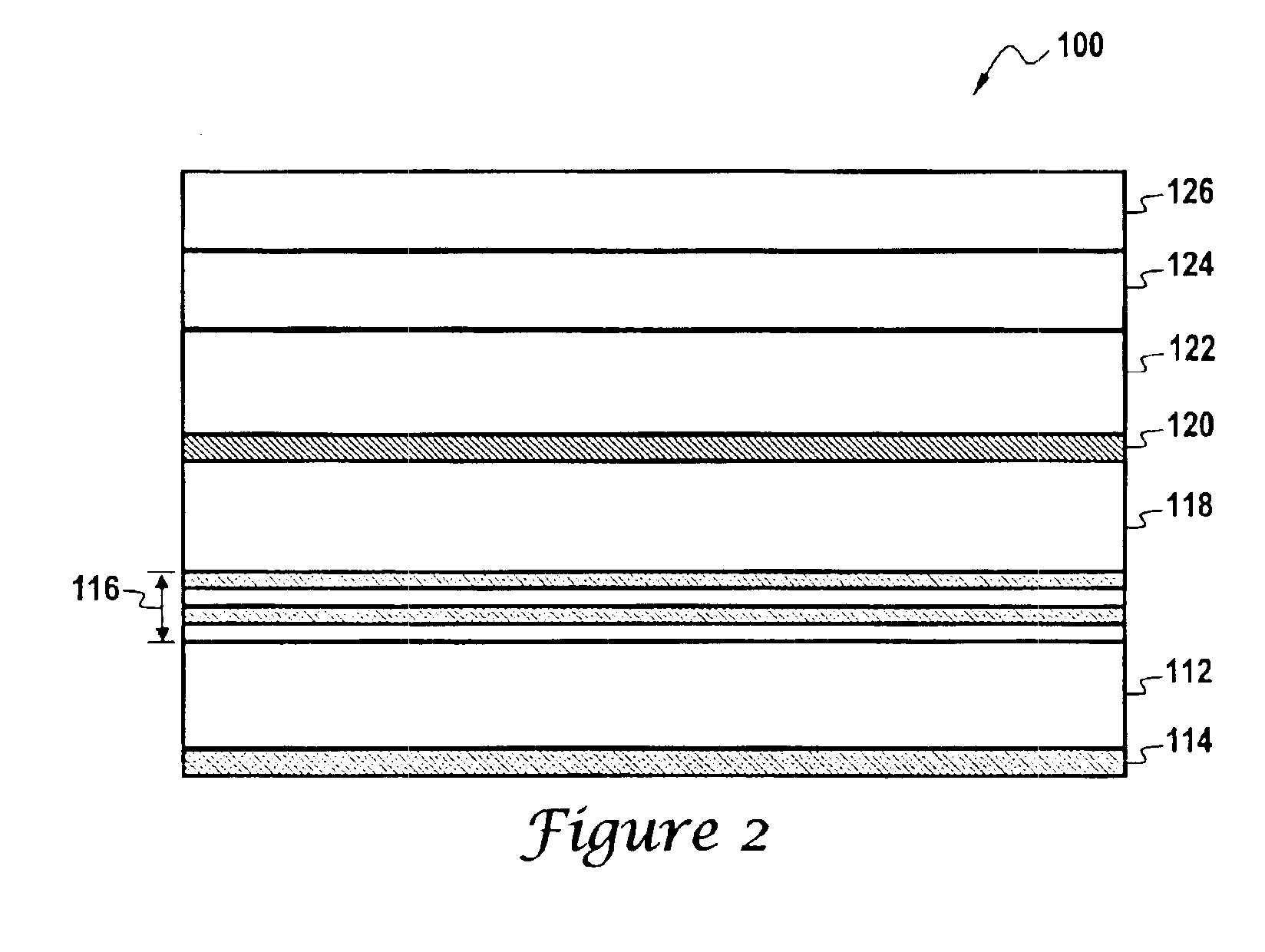
[0033]FIG. 2 illustrates a vertical cavity surface emitting laser (VCSEL) 100 that is in accord with the principles of the present invention. FIG. 2 should be understood as a simplified “cut-away” schematic depiction of a VCSEL that is generally configured as shown in FIG. 1. Thus, similar element numbers will be used for similar elements in FIG. 2 that were used in FIG. 1. However, the VCSEL 100 includes novel and useful top and bottom distributed Bragg reflectors (DBRs).

[0034]As shown in FIG. 2, the VCSEL 100 includes an n-doped indium phosphorus (InP) substrate 112 having an n-type electrical contact 114. An n-doped lower m...


PUM

PropertyMeasurementUnit
electrically conductiveaaaaaaaaaa
wavelengthaaaaaaaaaa
structureaaaaaaaaaa

Abstract

Distributed Bragg reflectors (DBRs), and VCSELs that use such DBRs, comprised of AlP layers on InP substrates. When grown on an InP substrate, if the critical layer thickness (tcrt) of AlP is greater than λ / 4nAlP, where nAlP is the index of refraction of InP and λ is the wavelength, then the DBR can be grown using alternating layers of InP and AlP, wherein the thickness of the AlP is less than the critical thickness. If the critical layer thickness (tcrt) of AlP is greater than λ / 4nAlP, then the DBR mirror is grown using alternating layers of InP and of an AlP / InP superlattice, wherein the AlP / InP superlattice is comprised of InP and of AlP wherein the thickness of the AlP is less than the critical thickness.

Description

UNITED STATES GOVERNMENT RIGHTS[0001]This invention was made with the United States Government support under 70NAHB8H4023 awarded by National Institute of Science and Technology (NIST). The United States Government has certain rights in the invention.CROSS-REFERENCE TO RELATED APPLICATIONS[0002]Not Applicable.BACKGROUND OF THE INVENTION[0003]1. Field of the Invention[0004]This invention relates to laser mirrors. More specifically, it relates to materials used for fabricating distributed Bragg reflector mirrors, and to distributed Bragg reflector mirrors made from those materials. Such distributed Bragg reflector mirrors are according to the principles of the present invention are suitable for use in vertical cavity surface emitting lasers (VCSELs).[0005]2. Discussion of the Related Art[0006]Vertical cavity surface emitting lasers (VCSELs) represent a relatively new class of semiconductor lasers. While there are many VCSEL variations, a common characteristic is that VCSELs emit light...

Claims


Application Information

Patent Timeline
Patent Type & Authority Patents(United States)
IPC IPC(8): H01S5/00H01S5/183H01S5/343
CPCB82Y20/00H01S5/183H01S5/34326H01S5/34306
Inventor KWON, HOKI
Owner II VI DELAWARE INC
Learn More