
High temperature superconducting tunable filter with an adjustable capacitance gap

a capacitance gap and superconducting technology, applied in the direction of superconductors/hyperconductors, variable capacitor structure combinations, resonance circuit tuning, etc., can solve the problems of radar warning systems that are often completely unusable, lumped element and distributed element filters suffer from these and other problems, and achieve low microphonics. , the effect of high speed

Inactive Publication Date: 2005-05-24
SUPERCONDUCTOR TECHNOLOGIES INC
View PDF17 Cites 34 Cited by
  • Summary
  • Abstract
  • Description
  • Claims
  • Application Information

AI Technical Summary

Benefits of technology

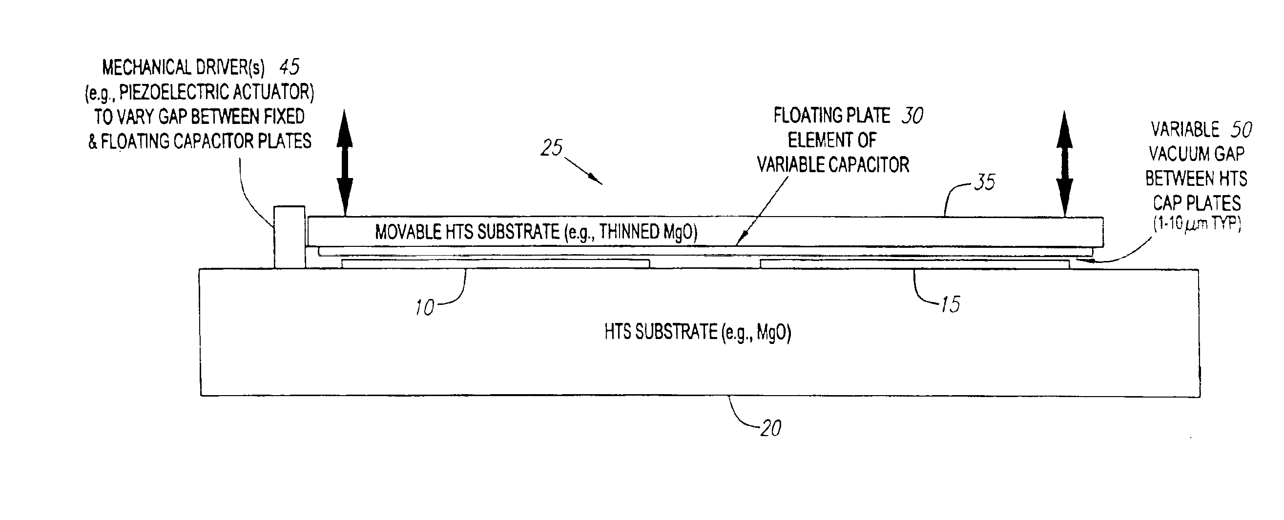
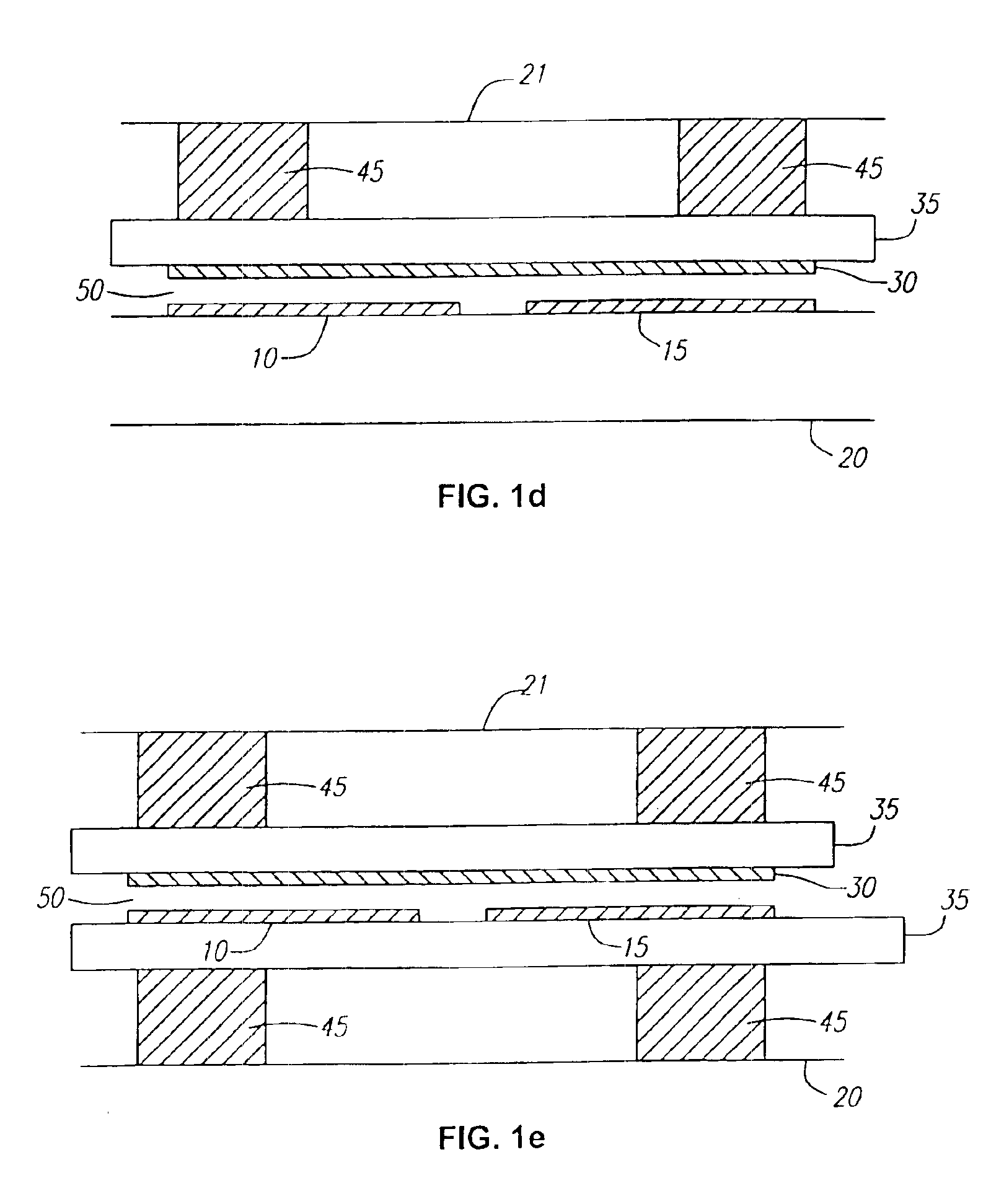
[0016]The mechanical driver provides a robust, fast and well-controlled variation in the gaps(s) between the movable plate and the fixed plate(s) of the variable capacitor. The mechanical driver may provide relatively high forces over plate gap changes of at least a few microns (and preferably 10 microns). The mechanical driver may incorporate conventional piezoelectric or electrostrictive ceramic actuator materials such as PZT (lead zirconate titanate) which provide length displacements on the order of 10−3 (the PZT actuator changes its total length approximately 0.1% in response the tuning signal). Alternatively, the mechanical driver may incorporate newer classes of materials such as higher-performance piezoelectric ceramics or electroactive polymer materials which provide a greater achievable mechanical displacement with respect to the dimensions of the mechanical driver. In response to a tuning signal, such materials have mechanical displacements that are more complex than the simple length displacements induced in a PZT actuator. However, the geometry of the mechanical driver may be altered to allow these alternate materials to be utilized.
[0018]The present invention avoids intermodulation problems by the use of a mechanical driver to affect the capacitance because the masses involved in the mechanical tuning processes do not allow substantial motion of the capacitor plates to occur at the signal frequencies of interest. In addition, the present invention permits the tuning signal and the filter signal to be de-coupled, avoiding the prior art problems associated with two-terminal designs. The present invention offers an extremely high Q, driven in one embodiment by piezoelectric actuators for tuning high speed and low microphonics.

Problems solved by technology

In most filter technologies, achieving a low insertion loss requires a corresponding compromise in filter steepness or selectivity.
In high-density signal environments, RADAR warning systems frequently become completely unusable.
Both lumped element and distributed element filters suffer from these and other problems.
For example, while distributed-element YIG-tuned filters have been used, the high level of insertion loss (usually greater than 10 dB) of suitable YIG filters necessitates their use on a “switch in when absolutely necessary” basis only, as the degradation to noise figure would generally be unacceptable.
Lumped element filters also suffer problems.
While varactors are simple and robust, they have limited quality factors (Q), and suffer from the problem that the linear process that tunes them extends all the way to the signal frequency, so that high-amplitude signals create, through the resulting nonlinearities, undesirable intermodulation products, etc.
The same problems of poor Q and high-frequency nonlinearities are anticipated for “tunable materials” such as ferroelectrics.
Unfortunately, this also leads to a serious associated disadvantage: limited dynamic range.
Unfortunately, for high signal amplitudes, this parametric modulation of the capacitance can produce severe cross-modulation (IM) effects between different signals, as well as harmonic generation and other undesirable effects.
While these signal-frequency varactor capacitance variations are the basis of useful devices such as parametric amplifiers, subharmonic oscillators, frequency multipliers, and many other useful microwave circuits, in the signal paths of conventional receivers they are an anathema.
As long as the εr (E) relationship applies out to the signal frequency, then the presence of the signal as a component of the E will lead to the same intermodulation problems that the varactors have.
In addition to the intermodulation / dynamic range problems of varactors, these conventional tuning devices also have serious limitations in Q, or tuning selectivity.
Considering that an interesting X-band (f=10 GHz) RADAR application might want a bandwidth of 20 MHz for the full width at half-maximum (FWHM), corresponding to a Q=500 quality factor, we see that available varactors have inadequate Q (too much loss) to meet such requirements.
An additional problem with both varactors and “tunable materials” for circuits with high values of Q is that these are basically two-terminal devices; that is, the dc tuning voltage must be applied between the same two electrodes to which the signal voltage is applied.
However, while the design of bias circuits that limit the loss of energy to a percent, or a fraction of a percent, even losses of a fraction of a percent are not nearly good enough for very high Q circuits (e.g., Q's in the 103 to >104 range, as achievable with HTS resonators).
In addition to their freedom from IM / dynamic range problems, normal metal plate MEMS variable capacitor structures offer the potential for substantially lower losses and higher Qs.
While this conventional MEMS variable capacitor structure is capable of improved Qs and avoids the intermodulation problems of varactors and “tunable materials,” it has some potential problems of its own.
A highly compliant suspension of even a small plate mass may render the device subject to microphonics problems (showing up as fluctuations in capacitance induced by mechanical vibrations or environmental noise).
Having the electric field which drives the plates directly in the (vacuum) signal dielectric gap may cause another problem.
Unfortunately, the minimum gap between the plates (maximum capacitance, and correspondingly, maximum danger of breakdown or “flash-over” failure between the plates) is achieved under exactly the wrong bias conditions: when the dc bias voltage is at a maximum.

Method used


Image

  • High temperature superconducting tunable filter with an adjustable capacitance gap
  • High temperature superconducting tunable filter with an adjustable capacitance gap
  • High temperature superconducting tunable filter with an adjustable capacitance gap

Examples


Embodiment Construction

[0035]Turning now to FIGS. 1a and 1b, a preferred embodiment for a high-Q bandpass filter resonator based on a MEMS-like HTS split-plate variable capacitor with independent mechanical actuation is illustrated. A first fixed plate 10 and a second fixed plate 15 are patterned from thin-film HTS material (e.g., YBCO) grown on a fixed substrate 20 (see, e.g., FIG. 1a) comprising, for example, MgO. Such epitaxial superconductive thin films are now routinely formed and commercially available. See, e.g., R. B. Hammond, et al., “Epitaxial Tl2Ca1Ba2Cu2O8 Thin Films With Low 9.6 GHz Surface Resistance at High Power and Above 77K,” Appl. Phy. Lett., Vol. 57, pp. 825-27, 1990. The variable capacitor structure 25 is completed by the addition of a floating plate 30 (drawn transparent in the plan view in FIG. 1b) patterned from thin-film HTS material grown on a movable substrate 35 (see, e.g., FIG. 1a) comprising, for example, MgO. Floating plate 30 is spaced apart and substantially parallel to fi...


PUM


Abstract

A tunable filter having a fixed substrate, a first and second plate comprising a high-temperature superconductor material on the fixed substrate, a movable substrate, a mechanical driver attached to the fixed substrate and the movable substrate, a floating plate comprising a high-temperature superconductor material on the fixed substrate wherein the floating plate, the first plate, and the second plate define a gap, and wherein the gap is varied by length changes in the mechanical driver is provided.

Description

CROSS-REFERENCE TO RELATED APPLICATIONS[0001]This is a continuation application of application Ser. No. 10 / 023,575, filed on Dec. 17, 2001, and issuing as U.S. Pat. No. 6,662,029 on Dec. 9, 2003, which is a continuation application of application Ser. No. 09 / 268,786, filed on Mar. 16, 1999, and issued as U.S. Pat. No. 6,347,237 on Feb. 12, 2002, the disclosures of which are hereby incorporated by reference.FIELD OF THE INVENTION[0002]This invention relates to a high temperature superconductor (HTS) tunable filter. More particularly, this invention relates to an HTS filter tunable by variation of a microelectromechanical capacitor.BACKGROUND OF THE INVENTION[0003]The need for a high-quality factor (Q), low insertion loss tunable filter pervades a wide range of microwave and RE applications, in both the military, e.g., RADAR, communications and electronic intelligence (ELINT), and the commercial fields such as in various communications applications, including cellular. Placing a sharp...

Claims


Application Information

Patent Timeline
IPC IPC(8): H01P7/08H01L39/00H01P1/20H01P1/203H01P7/00
CPCH01P7/082H01P7/088H01G5/40H01G5/16H03J2200/10Y10S505/866Y10S505/705Y10S505/70
Inventor EDEN, RICHARD C.WILLEMSEN, BALAM A.MATTHAEI, GEORGE L.
Owner SUPERCONDUCTOR TECHNOLOGIES INC
Learn More