
Feed-forward amplifier loop control utilizing if signal processing

a signal processing and loop control technology, applied in amplifiers, amplifiers with semiconductor devices/discharge tubes, amplifier modifications to reduce noise influence, etc., can solve problems such as poor cancellation, pilot leakage out of amplifiers, and intermodulation of pilot and desired signal, so as to achieve easy control or shield

Inactive Publication Date: 2005-05-24
INTEL CORP
View PDF6 Cites 8 Cited by
  • Summary
  • Abstract
  • Description
  • Claims
  • Application Information

AI Technical Summary

Benefits of technology

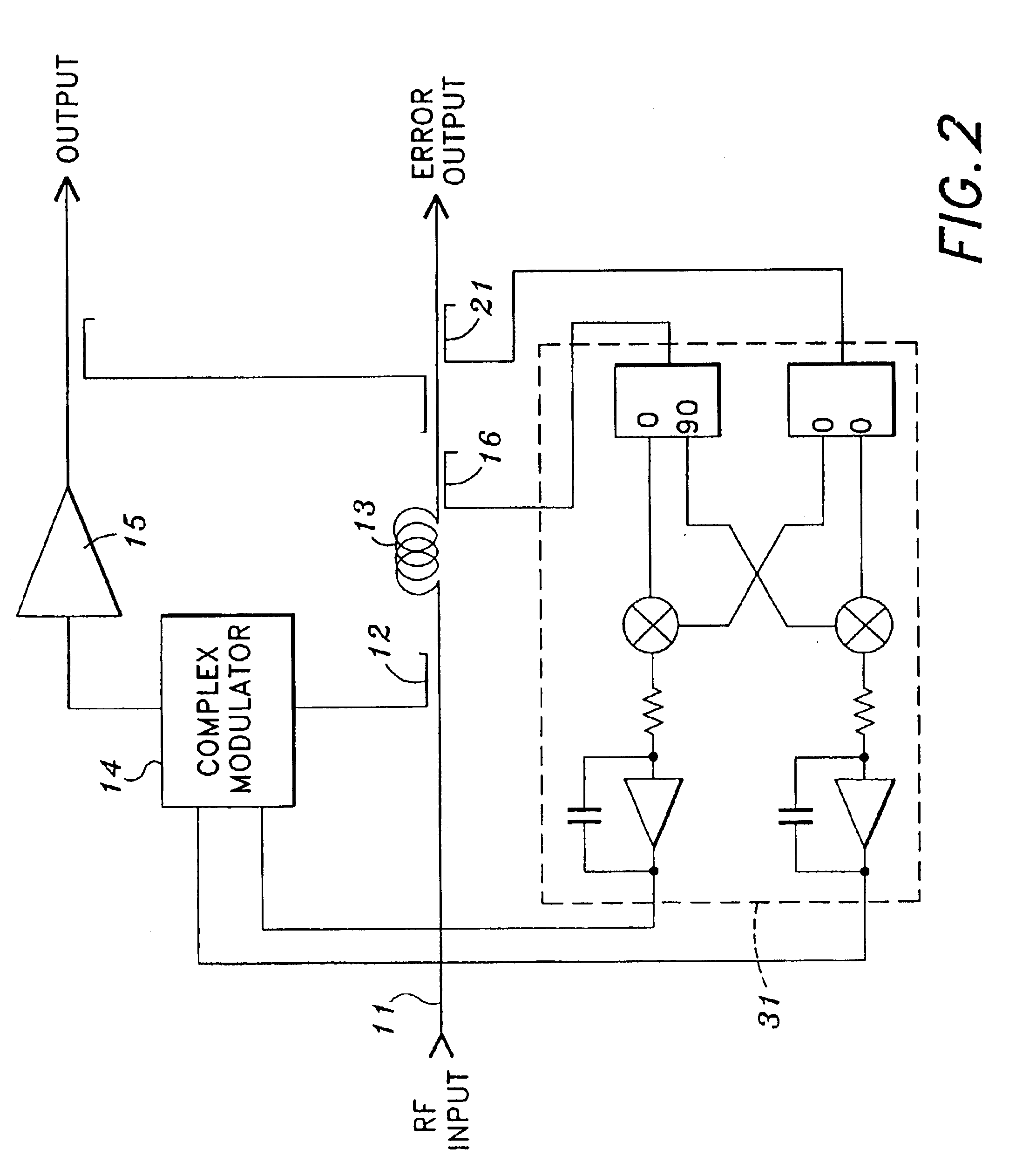
[0019]The differential cancellation eliminates the majority of DC drift and makes it possible for such a mixer, which is normally intended for use in the front ends of receivers, to be used successfully for control of the signal cancellation loop in feed-forward designs. Since the signal operating levels are very low, any distortion products created are much more easily controlled or shielded. An advantage of using such a device for signal cancellation control is the fact that it functions as a truly GHz (high frequency) linear multiplier. Since the device has virtually no threshold to overcome when processing signals, the result is at least an improvement of 10 dB in operating dynamic range over the diode method of signal mixing or detection.

Problems solved by technology

There are early designs that utilize pilot control, but they suffer from poor cancellation and pilot leakage out of the amplifier.
Practical limitations are that since the pilot is passed through a non-perfect amplifier with non-linearities, the pilot and desired signal are inter-modulated.
This inter-modulation prevents a satisfactory loop balance.
Another major drawback is the fact that since the signal is applied to the input of the system, the pilot is amplified along with the desired signals and appears at the system output, requiring a narrow band filter to remove this spurious pilot signal.
This causes a loss of output power due to the finite Q of a practical filter structure.
Another issue is the fact that since the actual signal is sampled, it is of utmost importance that the sampling period be longer than any envelope variations in the signal.
If the sampling period is close to the period of the variations in the envelope, the nulling algorithm will not be able to determine if a lower signal level is the result of a controller change or signal envelope change, causing an endless hunt to find a null point or possibly a loop oscillation.
However, this limitation can adversely affect the transient response to fast signal level changes such as the rapid changes in the number of carriers present or the carrier power.
Despite these advantages of the Cartesian loop or phase lock loop method, there are limitations and drawbacks.
One limitation is that implementation of such a Cartesian loop is usually accomplished using signal diodes as phase detectors.
This limits the dynamic range at low operating levels.
Although resulting in improved performance, this approach results in production of distortion products at relatively high levels due to the relatively high drive levels required to operate the diodes.
These products can leak into high gain portions of the amplifier system and will not be removed by the distortion cancellation process.
This method, relying on trial and error, results in prolonged loop lock time.

Method used


Image

  • Feed-forward amplifier loop control utilizing if signal processing
  • Feed-forward amplifier loop control utilizing if signal processing
  • Feed-forward amplifier loop control utilizing if signal processing

Examples


Embodiment Construction

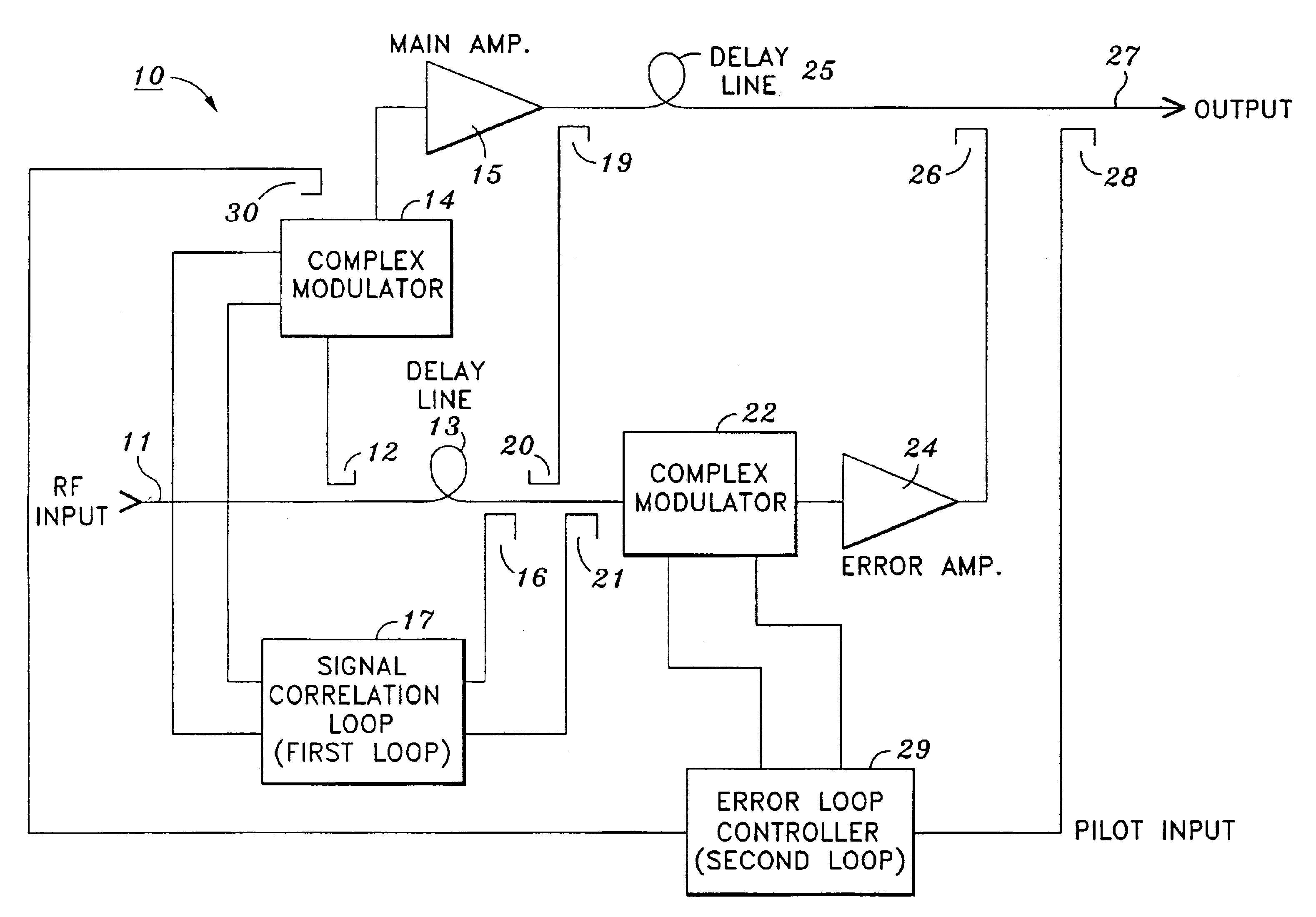
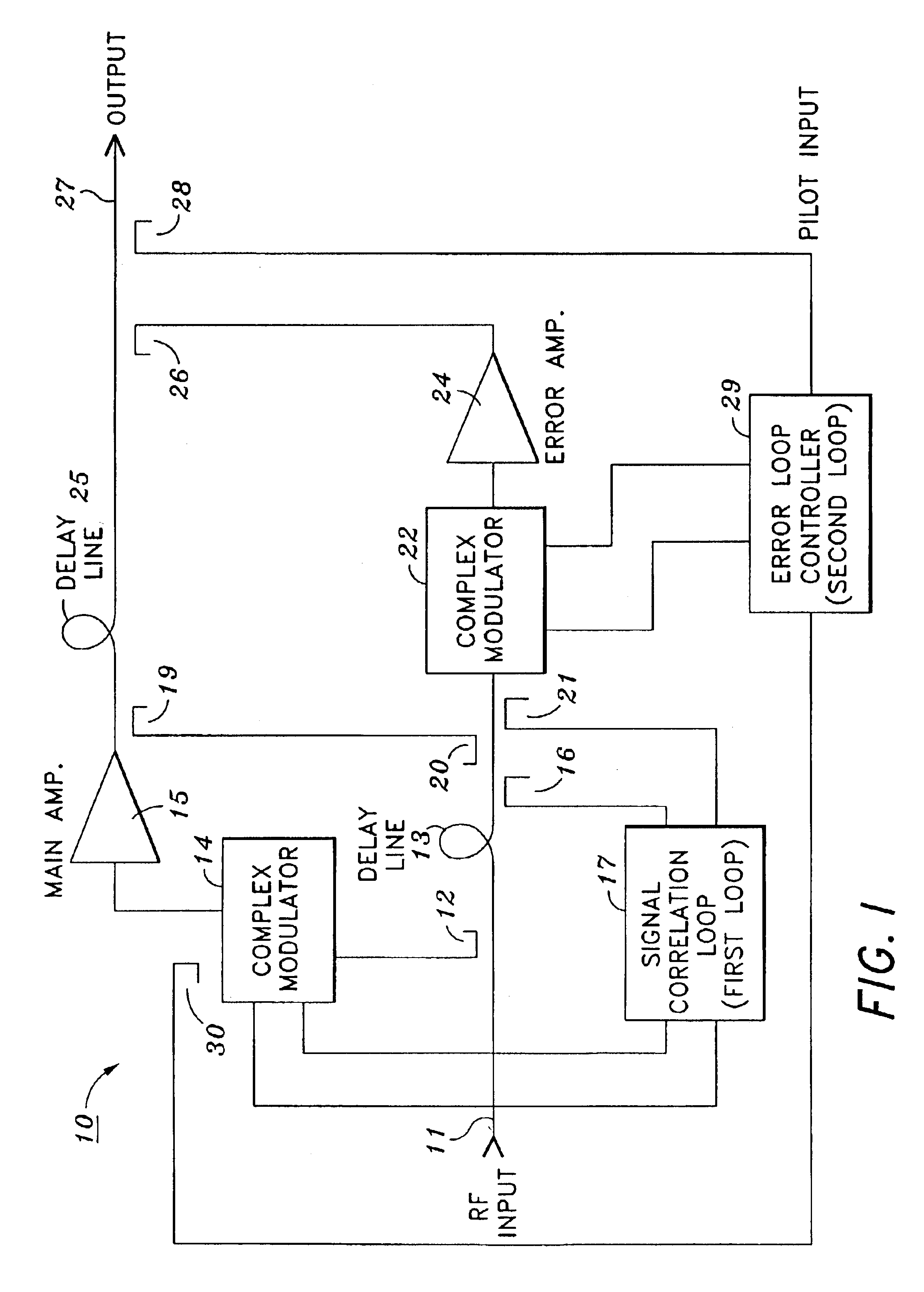
[0025]FIG. 1 shows a feed-forward amplifier 10 according to the invention. As shown in FIG. 1, RF input signal 11 is sampled by directional coupler 12 at approximately 10 dB down such that substantially all (approximately 90%) of the RF signal continues along delay line 13. The signal sampled by directional coupler 12 is fed to a complex (i.e., real and imaginary parts) modulator 14 and, following injection of the pilot signal from directional coupler 30, the signal is amplified at main amplifier 15. As for the RF input, it continues to propagate through delay line 13 where it is sampled by directional coupler 16 where it is fed as a reference to first loop 17 which is hereinafter referred to as a signal cancellation loop. Meanwhile, the output of main amplifier 15 is sampled by a sampling directional coupler 19 and coupled back into the RF input and subtracted (through appropriate phase coupling) by directional coupler 20. The signal from the main amplifier tends to cancel the RF i...


PUM


Abstract

An amplifier arrangement including a main amplifier to which feed-forward cancellation is applied, where the amplifier arrangement comprises an input for receiving signals to be amplified, an output for providing an amplified input signal, a pilot signal modulation circuit to generate a CW frequency shifted pilot signal, a mixer down for converting the pilot signal to an IF signal, and a sampling circuit for digitally sampling the IF signal. The amplifier arrangement includes a signal cancellation loop and a distortion cancellation loop each acting as an independent control function for minimizing pilot signal. The signal cancellation loop utilizes a Cartesian loop method for controlling the signal cancellation loop for sensing both phase and amplitude information simultaneously. The Cartesian loop uses a high frequency active mixer, which is a dual cross coupled differential pairs of devices capable of operating with input signals from near DC to 2.4 GHz, for control of the signal cancellation loop.

Description

[0001]This application is a national stage application of PCT / US01 / 50336, filed Dec. 21, 2001, which claims priority from U.S. Provisional Application No. 60 / 257,661, filed Dec. 22, 2000.BACKGROUND OF THE INVENTION[0002]1. Field of the Invention[0003]The present invention relates to a feed-forward amplifier, and particularly relates to a feed-forward signal cancellation control loop therein, as well as a feed-forward loop control utilizing IF signal processing.[0004]2. Description of the Related Art[0005]In a classical feed-forward control system there are two independent control functions occurring simultaneously. The first is a signal cancellation loop and the other is a distortion cancellation loop. Generally two methods of loop control exist. The first method is signal adaptive and the second is control indirectly by use of a pilot or internally generated signal. Each approach has advantages and disadvantages. Adaptive approaches operate on the desired signals or the spurious by...

Claims


Application Information

Patent Timeline
IPC IPC(8): H03F1/32H04B1/04
CPCH03F1/3235H04B2001/0441H03F1/3223H03F3/24
Inventor GENTZLER, CHARLES
Owner INTEL CORP
Learn More