
Membrane separation for sulfur reduction

a technology of sulfur reduction and membrane separation, which is applied in the direction of hydrocarbon purification/separation, hydrocarbon oil refining, and filtration. it can solve the problems of increasing operating costs, reducing the efficiency of hydrotreating, and reducing the volume of feed, so as to reduce the cost of sulfur reduction, improve economics, and reduce the effect of feed volum

Inactive Publication Date: 2005-05-24
WR GRACE & CO CONN
View PDF78 Cites 48 Cited by
  • Summary
  • Abstract
  • Description
  • Claims
  • Application Information

AI Technical Summary

Benefits of technology

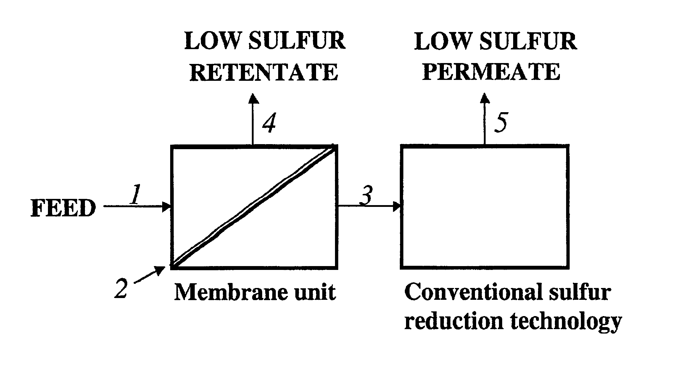
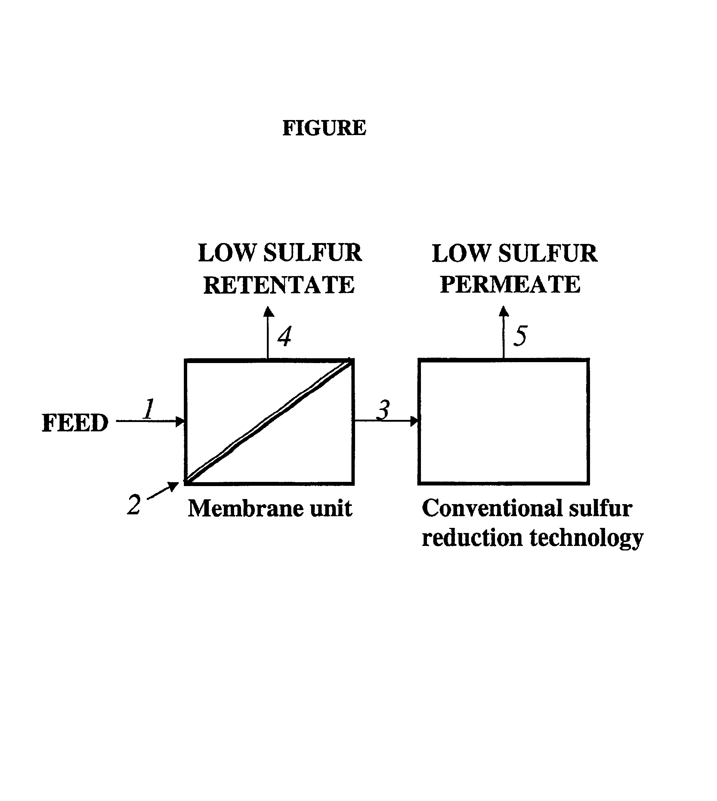
[0012]In accordance with the process of the invention, the sulfur deficient retentate comprises no less than 50 wt % of the feed and retains greater than 50 wt % of the initial olefin content of the feed. Consequently, the process of the invention offers the advantage of improved economics by minimizing the volume of the feed to be treated by conventional high cost sulfur reduction technologies, e.g. hydrotreating. Additionally, the process of the invention provides for an increase in the olefin content of the overall naphtha product without the need for additional processing to restore octane values.
[0013]The membrane process of the invention offers further advantages over conventional sulfur removal processes such as lower capital and operating expenses, greater selectivity, easily scaled operations, and greater adaptability to changes in process streams and simple control schemes.

Problems solved by technology

Sulfur in the gasoline is a direct contributor of SOx emissions, and it also poisons the low temperature activity of automotive catalytic converters.
A number of solutions have been suggested to reduce sulfur in gasoline, but none of them have proven to be ideal.
While hydrotreating allows the sulfur content in gasoline to be reduced to any desired level, installing or adding the necessary hydrotreating capacity requires a substantial capital expenditure and increased operating costs.
Further, olefin and naphthene compounds are susceptible to hydrogenation during hydrotreating.
This leads to a significant loss in octane number.
Hydrotreating the FCC naphtha is also problematic since the high olefin content is again prone to hydrogenation.

Method used


Image

  • Membrane separation for sulfur reduction
  • Membrane separation for sulfur reduction

Examples


example 1

[0047]A commercial pervaporation membrane (PERVAP® 1060) from Sulzer ChemTech, Switzerland, with a polysiloxane separation layer, was tested with a 5 component model feed (Table 1). The membrane shows a substantial permeation rate and an enrichment factor of 2.35 for thiophene. At the higher temperature with naphtha feedstock the mercaptans (alkyl S) had a 2.37 enrichment factor.

[0048]The same membrane was also tested with a refinery naphtha stream (Table 2). The compounds at the heavier end of this naphtha sample have higher boiling points than the operating temperature leading to lower permeation rates through the membrane for those components. Increase in temperature gives higher permeation rates.

[0049]The comparison of feed solutions between Tables 1 and 2 showed that solutions with both relatively high and low thiophene content can be enriched in the membrane permeate.

[0050]

TABLE 1Pervaporation experiments with model feedMembrane from Example 1FeedPermeatePermeateFeed temperatu...

example 2

[0052]A polyimide membrane was fashioned according to the methods of U.S. Pat. No. 5,264,166 and tested for pervaporation. A dope solution containing 26% Matrimid 5218 polyimide, 5% maleic acid, 20% acetone, and 49% N-methyl pyrrolidone was cast at 4 ft / min onto a non-woven polyester fabric with a blade gap set at 7 mil. After about 30 seconds the coated fabric was quenched in water at 22° C. to form the membrane structure. The membrane was washed with water to remove residual solvents, then solvent exchanged by immersion in 2-propanone, followed by immersion in a bath of equal mixtures of lube oil / 2-propanone / toluene bath. The membrane was air dried to yield an asymmetric membrane filled with a conditioning agent.

[0053]For pervaporation testing, the membrane was rinsed with the feed solution, and then mounted solvent wet in the cell holder. Results for a 5-component model feed are shown in Table 3. Curiously, the pervaporation performance improved at the higher temperature in both ...

example 3

[0055]Another polyimide membrane was fashioned according to the methods of U.S. patent application Ser. No. 09 / 126,261 and tested for pervaporation. A dope solution containing 20% Lenzing P84, 69% p-dioxane, and 11% dimethylformamide was cast at 4 ft / min onto a non-woven polyester fabric with a blade gap set at 7 mil. After about 3 seconds the coated fabric was quenched in water at 20° C. to form the membrane structure. The membrane was washed with water to remove residual solvents, solvent exchanged by immersion in 2-butanone, followed by immersion in a bath of equal mixtures lube oil / 2-butanone / toluene. The membrane was then air dried to yield an asymmetric membrane filled with a conditioning agent.

[0056]For pervaporation testing, the membrane was rinsed with the feed solution, and then mounted solvent wet in the cell holder. Results with naphtha are shown in Table 4. The membrane showed an enrichment factor of 4.69 for thiophene. Mercaptans (alkyl S) had a 3.45 enrichment factor....


PUM

PropertyMeasurementUnit
wt %aaaaaaaaaa
temperatureaaaaaaaaaa
pressureaaaaaaaaaa

Abstract

A membrane process for the removal of sulfur species from a naphtha feed, in particular, a FCC light cat naphtha, without a substantial loss of olefin yield is disclosed. The process involves contacting a naphtha feed stream with a membrane having sufficient flux and selectivity to separate a sulfur deficient retentate fraction from a sulfur enriched permeate fraction, preferably, under pervaporation conditions. Sulfur deficient retentate fractions are useful directly into the gasoline pool. Sulfur-enriched permeate fractions are rich in sulfur containing aromatic and nonaromatic hydrocarbons and are further treated with conventional sulfur removal technologies, e.g. hydrotreating, to reduce sulfur content. The process of the invention provides high quality naphtha products having a reduced sulfur content and a high content of olefin compounds.

Description

FIELD OF THE INVENTION[0001]The present invention relates to a process of reducing sulfur content in a hydrocarbon stream. More specifically, the present invention relates to a membrane separation process for reducing the sulfur content of a naphtha feed stream, in particular, a FCC cat naphtha, while substantially maintaining the initial olefin content of the feed.BACKGROUND OF THE INVENTION[0002]Environmental concerns have resulted in legislation which places limits on the sulfur content of gasoline. In the European Union, for instance, a maximum sulfur level of 150 ppm by the year 2000 has been stipulated, with a further reduction to a maximum of 50 ppm by the year 2005. Sulfur in the gasoline is a direct contributor of SOx emissions, and it also poisons the low temperature activity of automotive catalytic converters. When considering the effects of changes in fuel composition on emissions, lowering the level of sulfur has the largest potential for combined reduction in hydrocarb...

Claims


Application Information

Patent Timeline
Patent Type & Authority Patents(United States)
IPC IPC(8): C10G53/08C10G67/00C10G67/02C10G53/00C10G53/02C10G31/11C10G31/00B01D61/24B01D61/36B01D71/54B01D71/64B01D71/70C10G31/09
CPCC10G31/11C10G67/02C10G53/08C10G53/02
Inventor WHITE, LLOYD STEVENWORMSBECHER, RICHARD FRANKLINLESEMANN, MARKUS
Owner WR GRACE & CO CONN
Learn More