
Methods of using downhole polymer plug

a polymer plug and polymer technology, applied in the direction of wellbore/well accessories, fluid removal, sealing/packing, etc., can solve the problems of unsatisfactory sealing of unwanted zones, unsatisfactory cement sealing, and unsatisfactory contamination levels of the casing, etc., to achieve good long-term thermal stability, good chemical stability, and high deformation resistance

Inactive Publication Date: 2005-05-24
SHELL USA INC
View PDF42 Cites 66 Cited by
  • Summary
  • Abstract
  • Description
  • Claims
  • Application Information

AI Technical Summary

Benefits of technology

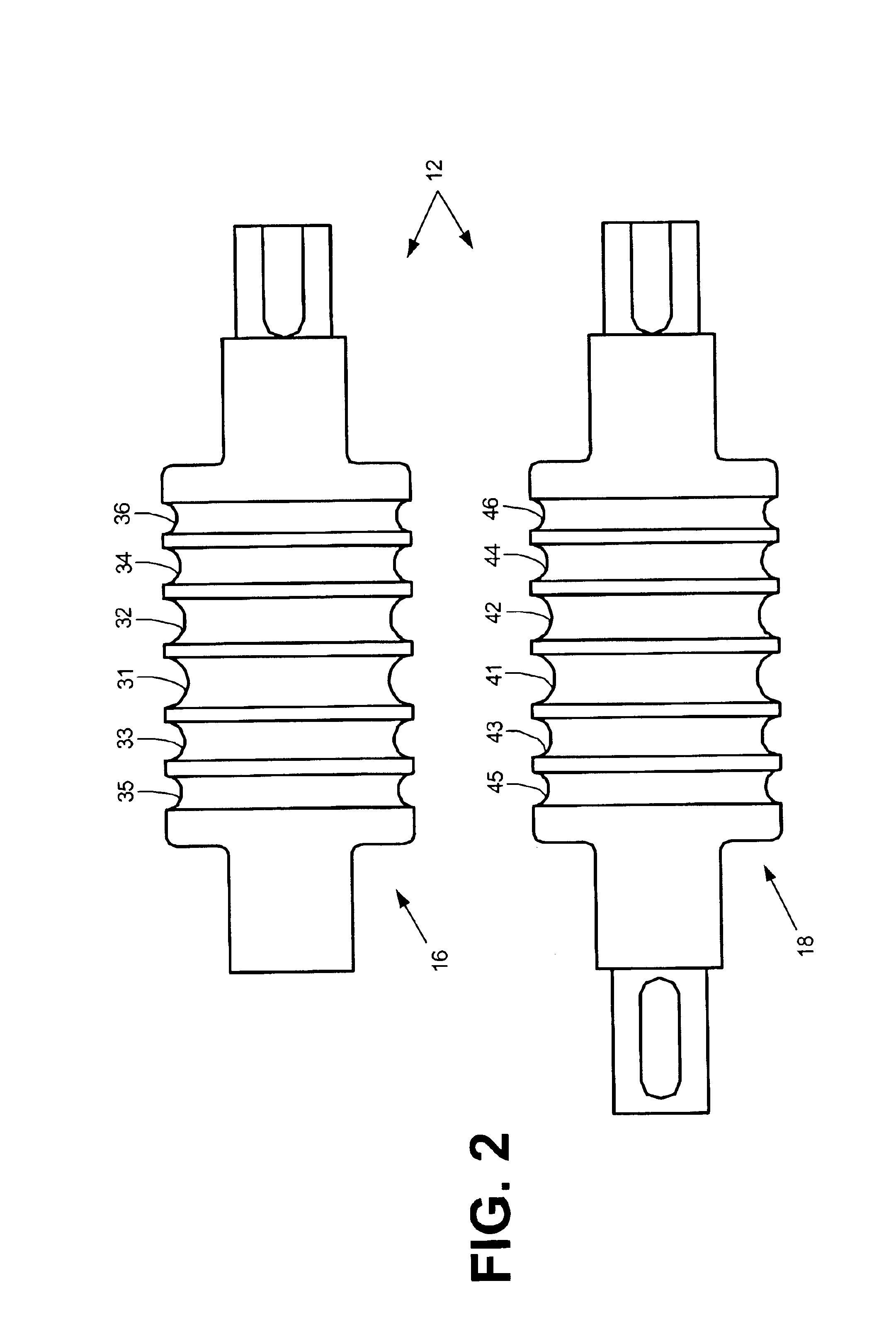
[0013]In one aspect, the present invention is directed to a method of plugging or lining a desired location within a wellbore by reducing the diameter of, and thereby creating stored energy in, a polymer member, then lowering the member to the desired location within the wellbore, and causing a reduction in the stored energy in the member to allow it to expand in diameter a sufficient amount to plug or line the wellbore at the desired location.
[0014]In another aspect, the invention relates to the member formed of a polymer having: (i) good long-term thermal stability to enable the member to maintain physical integrity throughout its intended service life; (ii) good chemical stability so that it is able to absorb crude, gas, or other downhole substances without embrittlement; (iii) high deformability so that it does not break during the creation of shape-memory; and (iv) quickly recoverable shape-memory upon the introduction of heat or a solvent capable of reducing the anelastic strain induced in the member

Problems solved by technology

Sometimes, during the life of the well, the perforations in a particular section of the casing may begin to admit an unacceptable level of contaminants.
For example, in the case of an oil well, unacceptable levels of water or sand may enter the wellbore from one or more production zones.
Sealing unwanted zones using cement, however, has often proved unsatisfactory because the cement tends to crack and permit water to leak into the production field.
Additionally, the removal and reinstallation of the production tubing requires significant time, effort, and cost.
The casings however, are intolerant of changes in wellbore diameter and may become stuck during deployment.
The use of these steel casings can involve significant effort and expense because the production tubing has to be pulled from the well before the expandable steel casing and installation equipment can be run down the hole.
Deficiencies also exist in the known methods of plugging a well where it has become damaged beyond repair or has reached the end of its useful life.
Cement plugs like cement liners, however, have been known to crack and allow fluid to leak through the plug.
The hydration of the pellets, however, is oftentimes uncontrollable.
For example, when the pellets are dropped down the wellbore they may stick to the sides of the casing or other equipment, and prematurely hydrate, thus clogging the wellbore and preventing effective sealing of the well.
Inflatable wireline plugs are not capable of withstanding high differential pressures without making additional runs to dump cement on top of the plug.
This makes it difficult to remove or mill up the plug if it is necessary to reenter the interval below the packer.

Method used


Image

  • Methods of using downhole polymer plug
  • Methods of using downhole polymer plug
  • Methods of using downhole polymer plug

Examples


Embodiment Construction

[0023]Thermoplastic polymers can store a large amount of mechanical energy upon deformation. When this energy is released, the anelastic strain of the polymer is recovered, and the polymer will return to its original shape.

[0024]Anelastic strain recovery is a kinetic process that generally proceeds more quickly with increasing temperatures. For amorphous polymers, like polystyrene, polycarbonate, polymethyl mathacrylate, the recovery is very fast at temperatures above their glass transition temperatures (Tg). For semi-crystalline polymers, such as polyethylene, PVDF, and Halar, the recovery is rapid at a temperature close to their melting point. Recovery of anelastic strain can also be obtained by exposing the polymers to certain solvents.

[0025]The present invention makes use of the anelastic strain recovery properties of particular polymers for plugging or lining a specific zone or location in a wellbore. The method includes providing a polymer member, preferably in the form of a r...


PUM


Abstract

Disclosed is a method of either plugging or lining a wellbore or casing using a polymer member into which stored energy or shape memory has been introduced. The shape memory is introduced into the member by reducing its diameter, such as by compressing the member using a rolling mill machine or stretching the member axially. Next, the member is lowered into a desired location in the wellbore or casing and subjected to conditions causing at least partial recovery of the anelastic strain. The conditions causing recovery of the anelastic strain can include heat from the reservoir surrounding the wellbore, heat introduced into the wellbore, solvents, and combinations thereof. Recovery of the anelastic strain causes the member to expand in diameter, thus plugging or lining the wellbore or casing at the desired location.

Description

BACKGROUND OF THE INVENTION[0001]1. Field of the Invention[0002]The present invention relates to wellbores, and more specifically, to methods and apparatus for selectively isolating areas such as production zones within the wellbore.[0003]2. Description of the Related Art[0004]After a well has been drilled and the casing is cemented into it, one or more sections of the casing are perforated. These perforations allow for the in-flow of fluids from the formation at one or more subterranean production zones. A production tubing is then inserted and installed into the well for the purpose of conducting fluids from the production zone to the surface.[0005]Sometimes, during the life of the well, the perforations in a particular section of the casing may begin to admit an unacceptable level of contaminants. For example, in the case of an oil well, unacceptable levels of water or sand may enter the wellbore from one or more production zones. Those production zones producing the excessive am...

Claims


Application Information

Patent Timeline
IPC IPC(8): E21B29/00E21B33/12E21B29/10E21B33/13
CPCE21B29/10E21B33/13E21B33/1208
Inventor CHANG, BENJAMIN TAI-ANZHANG, JANE QING
Owner SHELL USA INC
Learn More