Apparatus for beam homogenization and speckle reduction

a beam and beam technology, applied in the field of apparatus for beam homogenization and speckle reduction, can solve the problems of limiting the use of laser sources, affecting so as to and improve the quality of images.

Inactive Publication Date: 2005-05-17
JACOB JAMES JEFFERY +2
View PDF4 Cites 87 Cited by
  • Summary
  • Abstract
  • Description
  • Claims
  • Application Information

AI Technical Summary

Benefits of technology

[0008]This invention greatly improves the quality of images obtained using optical systems illuminated by coherent light. It does so by removing the undesirable psuedo-random variations in the final image due to interference speckle and inhomogeneities in the spatial intensity distribution of the light source. A special device, composed of a bundle of light-guiding fibers, is interposed between the illumination source and the imaging system. Each fiber is of slightly different length due to imperfections in manufacturing or deliberately introduced variations. These length differences are in general less than the coherence length of the illumination source, so that the light at the end of the bundle remains coherent. Each end of the fiber may in addition be arranged at different positions in the entrance and exit faces of the bundle to assist in homogenizing the intensity distribution. The incident illumination rays are distributed among the different fibers and propagate through the bundle along slightly different paths, depending upon the incidence angle and the position within the bundle. Each ray has thus accumulated a slightly different optical phase when it exits the device. This non-uniform propagation creates a psuedo-random phase variation across the illumination beam, which gives rise to an interference speckle pattern superimposed upon the desired image acquired by the optical system. This combination image is recorded by a detector, which may be a camera, or the human eye, or similar photo-sensitive device. The speckle pattern, although it initially appears random, is in fact a deterministic function of several factors, including fiber bundle position and orientation: if the fiber bundle is rotated in either direction, the speckle pattern changes, hence the description ‘dynamic’. This property is manipulated in order to remove the speckle. Rotating the fiber bundle around the axis of propagation, whilst simultaneously integrating the output of the photosensitive detector over a period of time thus washes out unwanted variations due to source inhomogeneities and coherent interference (‘speckle’). In general, longer integration times provide higher degrees of image speckle reduction. Note that any method which varies the propagation within the fiber bundle will have a similar smoothing effect on the interference speckle; for example, the fiber bundle could be translated perpendicularly to the beam direction. The fiber bundles are compact, scatter much less light than alternate techniques, and can be adapted for any wavelength of interest. The fiber bundles may be composed of solid-core fibers, for operation in the visible and near-IR and near-UV, or of hollow-core ‘capillary’ fibers for use in the far-IR and VUV regions of the spectrum. These techniques are especially useful for the design of short-wavelength (<200 nm) high-resolution laser microscopes.OBJECTS OF THE INVENTION

Problems solved by technology

However, there are two primary limitations to the use of such sources which must be overcome if high-quality images are to be obtained.
First, the images derived from systems illuminated with spatially and temporally coherent radiation often exhibit a psuedo-random interference pattern of light and dark regions across the entire field of view.
The speckle pattern is highly undesirable if quantitative information is required from the images, e.g., transmission measurements of a partially opaque object.
Further, the beams derived directly from laser sources often exhibit a spatial intensity distribution which is substantially non-uniform.
Often, these beams have additional small-scale intensity structure due to dust spots on mirrors, &c., which would mar the quality of the final image if not removed or compensated.
The first approach to speckle reduction reduces the optical coherence of the illumination source to the point that there is insufficient interference to produce visible speckle patterns.
Elimination of the optical coherence is an attractive choice because no temporal averaging is required, hence throughput is increased, but is often prohibitively difficult.
The optical arrangement to perform this operation using discrete optical components is quite bulky and suffers from low overall throughput, and is not suitable for long-coherence length sources, e.g., single-frequency lasers.
The disadvantage of this method is that the diffusers (since they scatter light so effectively) are extremely lossy; often less than {fraction (1 / 1000)}th of the available illumination light is available for actual imaging.
This problem precludes use of the diffuser technique at difficult-to-produce illumination wavelengths, especially in the vacuum ultraviolet (VUV).

Method used


Image

  • Apparatus for beam homogenization and speckle reduction
  • Apparatus for beam homogenization and speckle reduction
  • Apparatus for beam homogenization and speckle reduction

Examples


Embodiment Construction

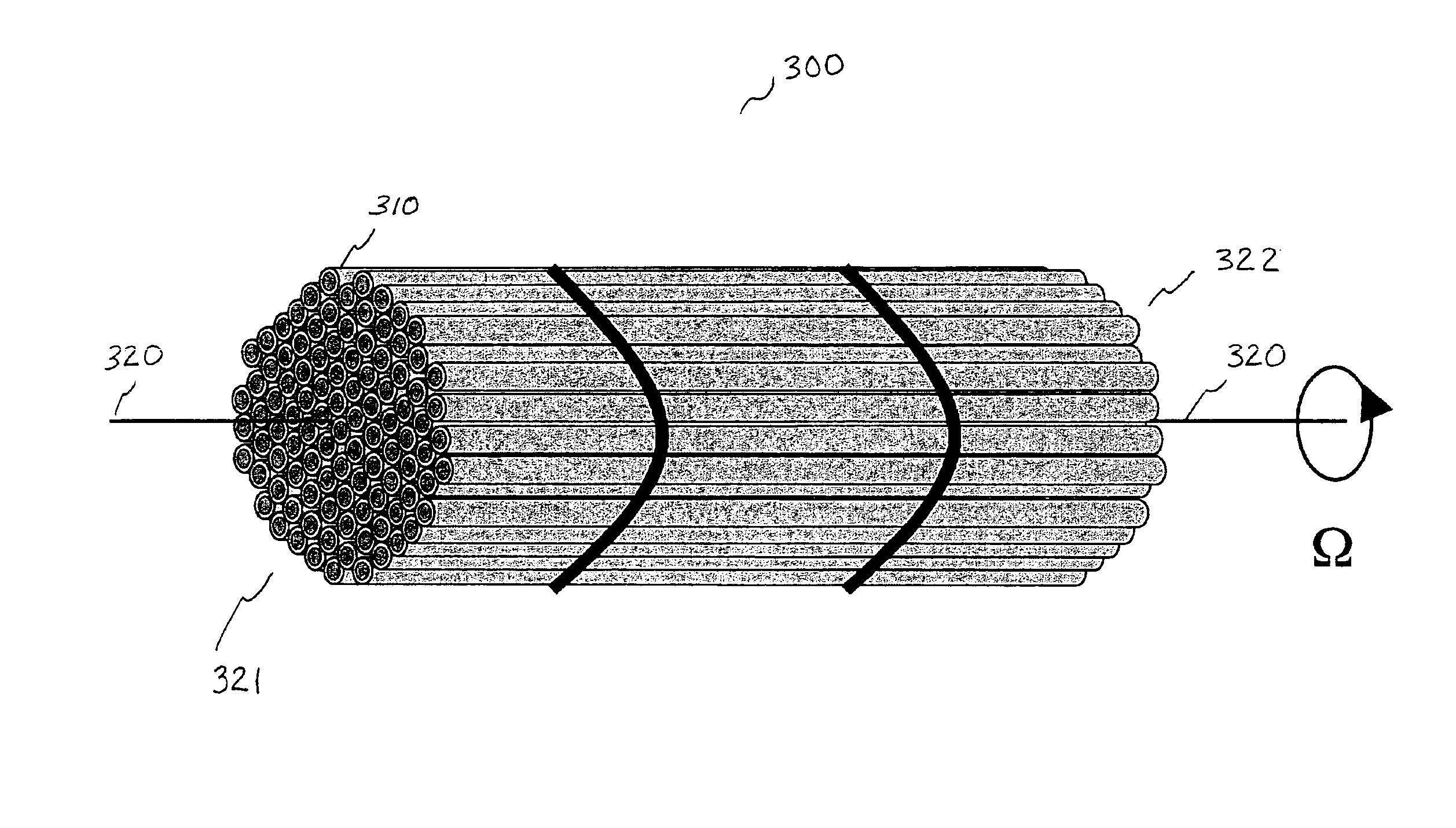
[0015]The present invention combines the steps of temporal averaging and dynamic speckle pattern generation to accomplish spatial homogenization and speckle reduction. Our technique for division and re-combination uses an array or bundle 300 of light guides 310, as shown in FIG. 3. The array may be arranged so that the exit 322 and entrance 321 faces have different geometries to accomplish beam shaping (e.g., from rectangular to circular). To the imaging system, the illumination now seems to arise from a number (often several hundred) of partially-coherent, small circular apertures. Propagation through the light guide array homogenizes the beam and reduces the coherence of the laser light. A collection of fibers (either optical or capillary tube) is fused together, the number depending upon the desired aperture and core diameter. The whole assembly may be rotated along the axis of optical propagation 320 in either direction at some rotation rate Ω, or translated across the face perp...


PUM


Abstract

This invention greatly improves the quality of images obtained using optical systems illuminated by coherent light. It does so by removing the undesirable psuedo-random variations in the final image due to interference speckle and inhomogeneities in the spatial intensity distribution of the light source. A bundle of light-guiding fibers is interposed between the illumination source and the imaging system. Non-uniform propagation within the fiber bundle creates a psuedo-random phase variation across the illumination beam, which gives rise to a dynamic interference speckle pattern superimposed upon the desired image acquired by the optical system. Rotating the fiber bundle around the axis of propagation, whilst simultaneously integrating the output of the photosensitive detector over a period of time, substantially removes variations due to source inhomogeneities and coherent interference.

Description

CROSS-REFERENCE TO RELATED APPLICATION[0001]This application claims the benefit of U.S. Provisional Patent Application Ser. No. 60 / 380,556, “Laser speckle reducer” by J. J. Jacob and T. Litvin, filed May 13, 2002, which is incorporated herein by reference.BACKGROUND OF THE INVENTION[0002]Lasers and other coherent light sources are attractive illumination sources for optical microscopes and other image-forming systems due to their high brightness and monochromaticity. However, there are two primary limitations to the use of such sources which must be overcome if high-quality images are to be obtained. First, the images derived from systems illuminated with spatially and temporally coherent radiation often exhibit a psuedo-random interference pattern of light and dark regions across the entire field of view. This interference pattern is known as speckle and is due to the interference of the coherent light scattered from different points on the object. The speckle pattern is highly und...

Claims


Application Information

Patent Timeline
IPC IPC(8): G02B27/09G02B6/06G02B27/48
CPCG02B6/06G02B27/48G02B27/0994
Inventor JACOB, JAMES JEFFERYLITVIN, TIMOTHYMERRIAM, ANDREW JOHN
Owner JACOB JAMES JEFFERY
Why Eureka
Try Eureka