
Flash memory cell programming method and system

a flash memory cell and programming method technology, applied in the field of memory programming, can solve the problems of reducing the chances of excessive correction of over-erased memory cells, and achieve the effects of fast programming of flash memory cells, increased electrical field strengths, and convenient and quick operation of flash memory cells

Inactive Publication Date: 2005-05-17
INFINEON TECH LLC
View PDF2 Cites 17 Cited by
  • Summary
  • Abstract
  • Description
  • Claims
  • Application Information

AI Technical Summary

Benefits of technology

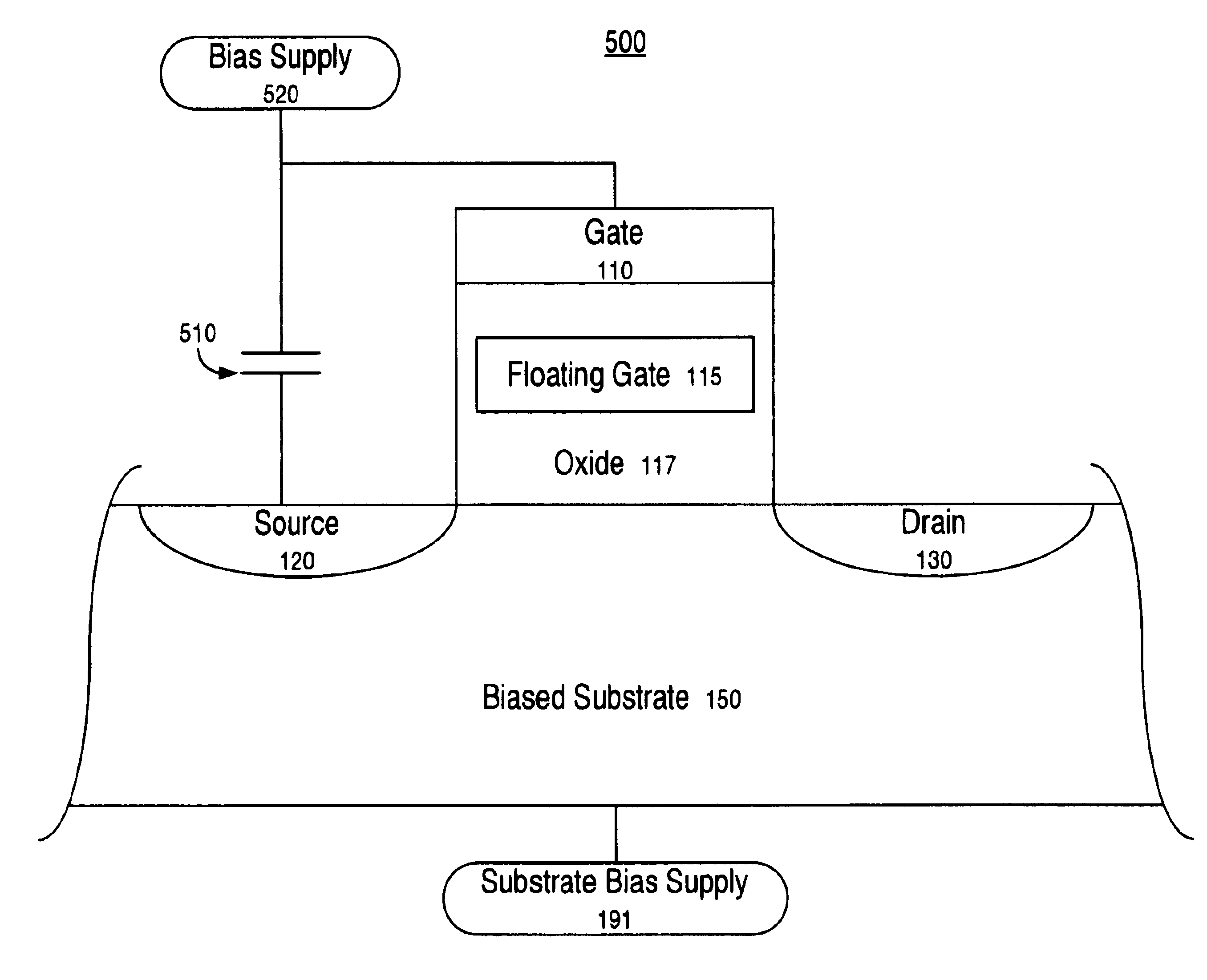
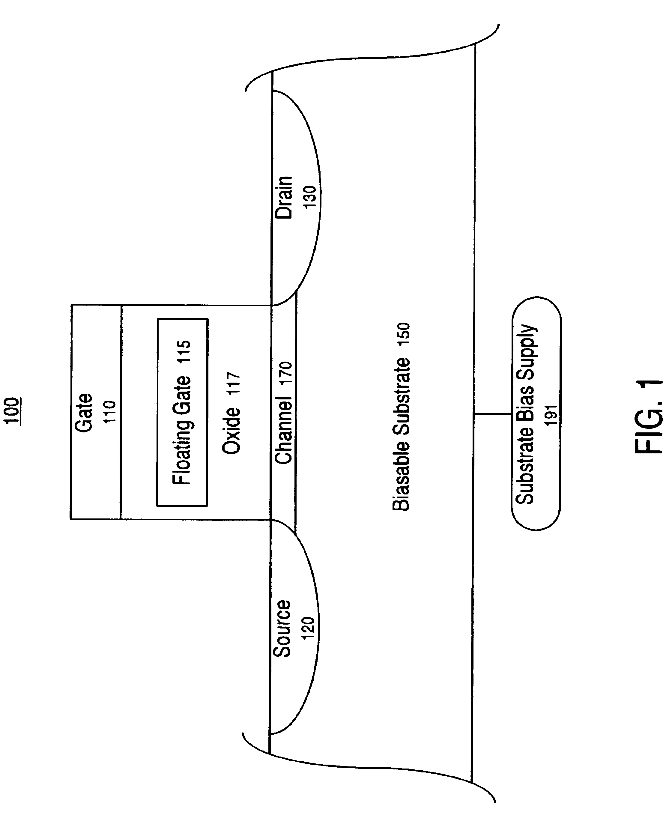
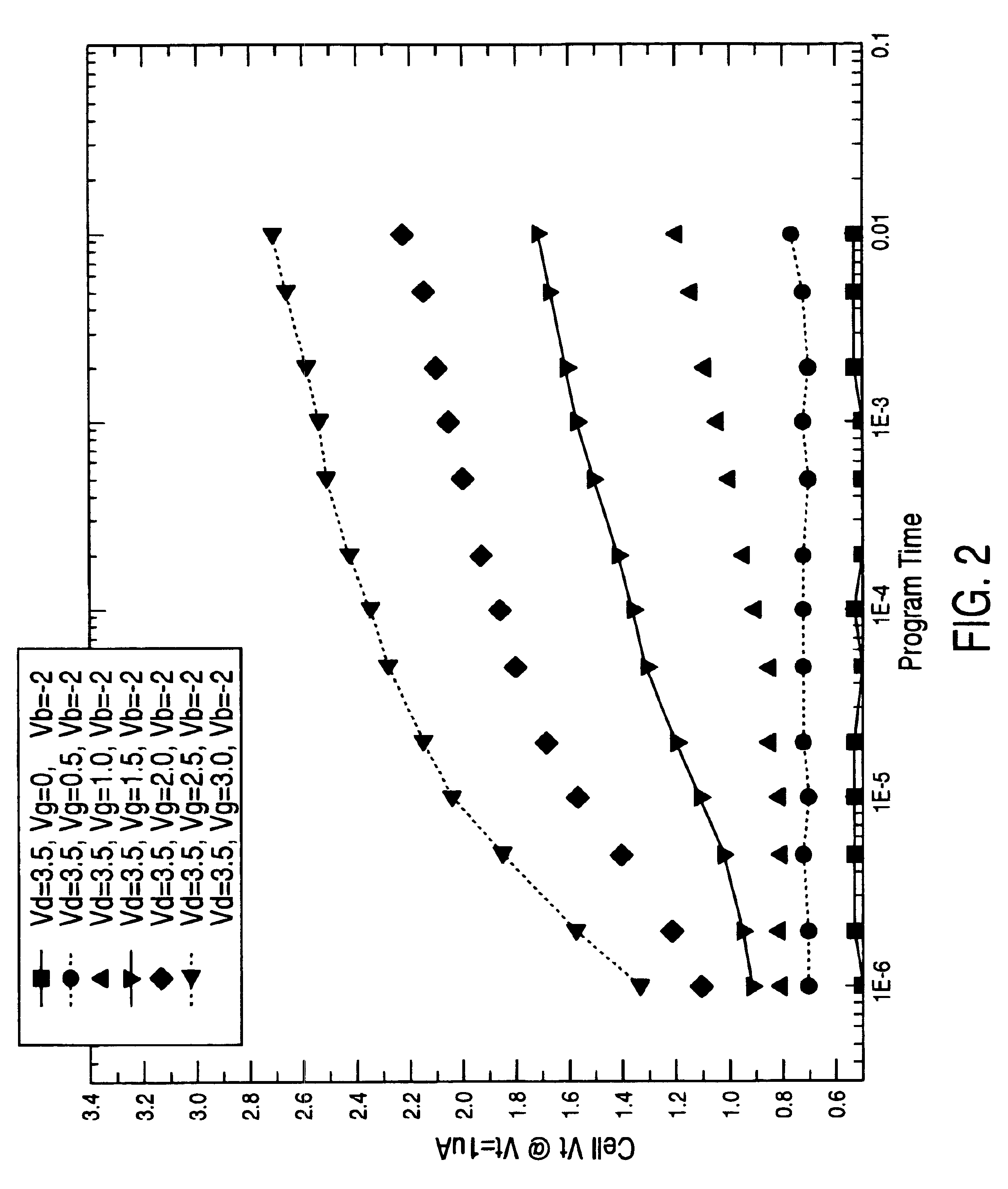
[0008]The present invention is a flash memory programming system and method that facilitate efficient and quick operation of a flash memory cell by providing a biasable well (e.g., substrate). In one embodiment, a present invention flash memory cell programming system and method include a biasable well (e.g., substrate) that enables increases in electrical field strengths which assist charge alteration in a floating gate of the flash memory cell. The electric fields provide additional force that aids the charge movement though a dielectric barrier (e.g., oxide) around a charge trapping region (e.g., a floating gate). The assistance from the electric field enables faster programming of the flash memory cell. The present biasable well system and method also create a self convergence point that increase control during programming operations and reduces the chances of excessive correction for over erased memory cells. The biasing can also facilitate reduction of stress on a drain voltage pump, reduction of leakage current, and reduction of programming durations. Some implementations also include a biasable gate, biasable source and biasable drain in a flash memory cell.

Problems solved by technology

The present biasable well system and method also create a self convergence point that increase control during programming operations and reduces the chances of excessive correction for over erased memory cells.

Method used


Image

  • Flash memory cell programming method and system
  • Flash memory cell programming method and system
  • Flash memory cell programming method and system

Examples


Embodiment Construction

[0016]Reference will now be made in detail to the preferred embodiments of the invention, examples of which are illustrated in the accompanying drawings. While the invention will be described in conjunction with the preferred embodiments, it will be understood that they are not intended to limit the invention to these embodiments. On the contrary, the invention is intended to cover alternatives, modifications and equivalents, which may be included within the spirit and scope of the invention as defined by the appended claims. Furthermore, in the following detailed description of the present invention, numerous specific details are set forth in order to provide a thorough understanding of the present invention. However, it will be obvious to one ordinarily skilled in the art that the present invention may be practiced without these specific details. In other instances, well known methods, procedures, components, and circuits have not been described in detail as not to unnecessarily o...


PUM


Abstract

A flash memory cell programming system and method that facilitate efficient and quick operation of a flash memory cell by providing a biasable well (e.g., substrate) is presented. The biasable well flash memory cell enables increases in electrical field strengths in a manner that eases resistance to charge penetration of a dielectric barrier (e.g., oxide) around a charge trapping region (e.g., a floating gate). The present biasable well system and method also create a self convergence point that increase control during programming operations and reduces the chances of excessive correction for over erased memory cells. The biasing can assist hard programming to store information and / or soft programming to correct the effects of over-erasing. The biasing can also reduce stress on a drain voltage pump, reduce leakage current and reduce programming durations. Some implementations also include a biasable control gate component, biasable source component and biasable drain component.

Description

TECHNICAL FIELD[0001]The present claimed invention relates to the field of memory programming. More particularly the present invention is associated with a soft programming method for short channel NOR flash cells.BACKGROUND ART[0002]Electronic systems and circuits have made a significant contribution towards the advancement of modem society and are utilized in a number of applications to achieve advantageous results. Numerous electronic technologies such as digital computers, calculators, audio devices, video equipment, and telephone systems have facilitated increased productivity and reduced costs in analyzing and communicating data, ideas and trends in most areas of business, science, education and entertainment. Frequently, these advantageous results are realized through the use of information stored on a memory media and manipulated by a processing device. The type of memory storage medium can have significant impacts on the performance of an information processing system.[0003...

Claims


Application Information

Patent Timeline
IPC IPC(8): G11C16/04G11C11/56H01L29/423H01L29/788
CPCG11C11/5621H01L29/7883H01L29/42324G11C16/0416
Inventor PARK, SHEUNGHEEHADDAD, SAMEER S.CHANG, CHIFASTOW, RICHARD M.KWAN, MING SANGWANG, ZHIGANG
Owner INFINEON TECH LLC
Learn More