
Molded foam articles prepared with reduced mold residence time and improved quality

a technology of molded foam and residence time, applied in the direction of coatings, etc., can solve the problems of severe practical limits on the minimum mold residence time, part to swell and/or crack, and part unsuitable for us

Inactive Publication Date: 2005-05-03
HUNTSMAN INT LLC +1
View PDF11 Cites 47 Cited by
  • Summary
  • Abstract
  • Description
  • Claims
  • Application Information

AI Technical Summary

Benefits of technology

[0017]Yet a further aspect of the invention is a reaction system which is suitable for the production of expanded moldings by the RIM process wherein viable moldings can be more consistently produced, relative to prior art systems, within 65 seconds from the point that injection is completed without an increase in post-blow damage, relative to the same articles made from the same system and demolded 105 seconds after injection is completed (using the same processing equipment and process conditions).
[0018]Still further aspects of the invention include a process for making expanded moldings of consistently high quality with reduced processing cycle time, and moldings prepared according to such process.

Problems solved by technology

This need is strongest in the LD-S-RIM area, where foaming places severe practical limits on the minimum mold residence time per part.
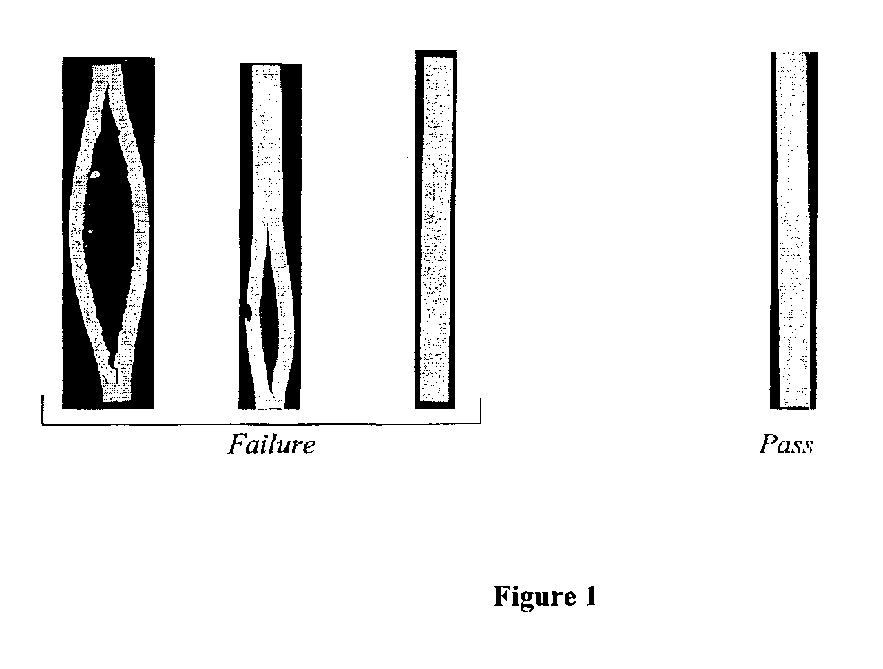
Even when the molded part has cured to the point where it is strong enough to be demolded without damage, the liberation of gas from the polymer can cause the part to swell and / or crack after the mold has been opened and even after the part has been completely removed from the mold.
The swelling and / or cracking render the part unsuitable for use.
This process, known commonly as “post blow”, can result in grotesque internal splits and / or part swelling.
The problem is most severe in thick parts, or thick sections of parts.
According to this conjecture the dissolved gas comes out of solution when the mold pressure is released, resulting in splits and voids unless the polymer has reached a very advanced state of cure.
As the mold residence time is reduced below about 105 seconds, using the polyurethane urea LD-S-RIM systems of the prior art, a majority of the parts are of unacceptable quality (scrap).
A high scrap rate is clearly undesirable for the economics of the process, and also for environmental reasons.
In large scale molding operations, common in the automotive industry, a scrap rate of greater than 5% would be unacceptable regardless of how short the mold residence time.
The post mold expansion (post blow) problem described above causes defects in part quality that cause scrap rates to go up quickly as mold residence times are reduced.
These defects include internal splits and / or cracking that are visible at the surface of the part.
Splits are especially problematic in thick parts or thick sections of parts.
This will result in a part being scrapped.
Obviously, a split that is directly visible on the surface will also result in the part being scrapped.
These large surface (or near-surface) bubbles can be seen in the surface of the part, and make it cosmetically unacceptable.
Although the presence of such large surface-visible defects (sometimes referred to as voids; blisters; or as de-lamination, in the case of very large bubbles behind impervious facings) can sometimes be fixed (i.e., by puncturing the facing above the bubble or filling the area of the void where necessary), these large visible defects usually result in scrap parts.
If the area of interfacial non-adhesion (bubble) is large enough it will become quite an obvious defect, since trapped gases within the part will collect in this non-adhering interfacial area and raise a large bubble under the facing material.
The presence of a surface-visible void or bubble of greater than an inch across (at its widest point) will result in a molded part being scrapped.
In fact, a surface-visible void or bubble of greater than one half inch across will usually result in a part being discarded as scrap.
This dramatic further improvement is currently not possible, because of defects caused by post blow phenomena.

Method used


Image

  • Molded foam articles prepared with reduced mold residence time and improved quality

Examples


example 1

[0241]According to the fast demold protocol, 45 screening evaluations were conducted using the base polyol blend shown in Table I. Table II outlines the fast demold results for various surfactants and surfactant concentrations. The concentrations of surfactant 1 and surfactant 2 noted in Table II are weight percentages relative to the total blend weight of surfactant and polyol blend of Table I. The isocyanate used with the system in Table I was RUBINATE® 8700 isocyanate. The weight ratio of the isocyanate to polyol blend was 1.67, and the total reaction mixture blend weight was 175-g. This blend weight results in a molded density of approximately 0.37-g / cm3.

[0242]

TABLE IComponentWeight Percent (%)JEFFOL ® G30-650 polyol76.47Glycerine5.74POLYCAT ® 8 catalyst2.68DABCO ® 8800 catalyst0.76LOXIOL ® G71S polyester7.65UNITOL ® DSR fatty acid4.97KEMESTER ® 5721 tridecyl octadecanoate0.84Water0.89

[0243]

TABLE IIConcentrationConcentrationof Surfactantof Surfactant1 in TABLE I2 in TABLE IFast ...

example 2

[0244]In accordance with the fast demold protocol, 11 screening tests were conducted using the polyol blend shown in Table III. Table IV outlines the fast demold results for the various fatty esters and fatty ester concentrations. The fatty ester concentrations noted in Table IV are weight percentages relative to the total blend weight of fatty ester and polyol blend of Table III. The isocyanate used with the system in Table III was RUBINATE® 8700 isocyanate. The weight ratio of the isocyanate to polyol blend was 1.61, and the total reaction mixture blend weight was 175-g. This blend weight results in a molded density of approximately 0.37-g / cm3.

[0245]

TABLE IIIComponentWeight Percent (%)JEFFOL ® G30-650 polyol82.06Glycerine6.15POLYCAT ® 8 catalyst2.87DABCO ® 8800 catalyst0.82UNITOL ® DSR fatty acid5.33KEMESTER ® 5721 tridecyl octadecanoate0.91REACTINT ® X77 colorant0.33NIAX ® L550 surfactant0.81Water0.72

[0246]

TABLE IVConcentration of fattyester in TABLE IIITestPolyol BlendFast Demol...

example 3

[0247]Table V shows fast demold performance for several screening tests. All formulations are tested according to the fast demold protocol with the exception of the 3.5 overpack guideline; all systems were blended such that the total reaction mixture blend weight was 175-g. This blend weight results in a molded density of approximately 0.37-g / cm3. RUBINATE® 8700 isocyanate was the isocyanate used for all polyol blends in Table V. The A / B value refers to the weight ratio of the isocyanate to the polyol blend.

[0248]

TABLE VFormulation NumberWeight Percent (%)Polyol Blend123456789JEFFOL ® G30-65080.41 77.34 74.95 71.75 75.40 75.25 75.09 ——polyolGlycerine6.035.805.625.385.655.645.635.445.97Polyol A————————73.77 DALTOLAC ® P130———————67.23 —polyoldipropylene glycol———————7.92—JEFFCAT ®————————1.74PMDETA catalystJEFFCAT ® DMCHA2.332.712.622.512.642.632.631.58—catalystDABCO ® 88000.760.770.750.720.750.750.750.40—catalystNIAX ® L5500.800.770.740.711.001.001.001.000.50surfactantNIAX ® L6980——...


PUM

PropertyMeasurementUnit
Fractionaaaaaaaaaa
Temperatureaaaaaaaaaa

Abstract

Foamed molded articles produced by reaction injection molding (RIM) are provided. The molded articles are formed by reaction of a polyisocyanate component with an isocyanate reactive component in a mold using a blowing agent. The molded articles are preferably composites formed in the presence of a fibrous reinforcing material. The foamed articles are characterized by relatively short minimum mold residence times, and can thereby be produced more economically than prior art composites. The foamed articles are further characterized by a reduction in physical defects, such as splits and voids.

Description

CROSS-REFERENCE TO RELATED APPLICATIONS[0001]This application is a continuation of international application PCT / US02 / 01754, filed Jan. 23, 2002, and claims priority to U.S. Provisional Application Ser. No. 60 / 263,706, filed Jan. 24, 2001; U.S. Provisional Application Ser. No. 60 / 267,246, filed Feb. 8, 2001; U.S. Provisional Application Ser. No. 60 / 272,444, filed Mar. 1, 2001; and U.S. Provisional Application Ser. No. 60 / 292,244, filed May 18, 2001.FIELD OF THE INVENTION[0002]The present invention relates to improvements in the preparation of high quality expanded moldings by the reaction injection molding process. More specifically, it relates to improvements to the cycle time, and hence the economics, of the production of low density reactively processed molded articles, from the reaction of a polyisocyanate component with an isocyanate reactive component, preferably in the presence of water as a foaming agent.BACKGROUND OF THE INVENTION[0003]The reaction injection molding process...

Claims


Application Information

Patent Timeline
IPC IPC(8): B29C67/24C08G18/00C08G18/40C08G18/34B29C45/00C08G18/42C08G18/66C08G101/00C08L75/04
CPCB29C67/246C08G18/34C08G18/4018C08G18/4288C08G18/6674C08L75/04C08G2101/0008C08G2101/0066C08G2101/0083C08G2120/00C08G2125/00C08L83/00C08G2110/0008C08G2110/0066C08G2110/0083
Inventor SHIDAKER, TRENT A.BAREIS, DAVID W.GILLIS, HERBERT R.
Owner HUNTSMAN INT LLC
Learn More