Low spurious charge pump

a charge pump and low-spurious technology, applied in the direction of pulse automatic control, oscillator generator, pulse technique, etc., can solve the problem of spurious output current, and achieve the effect of reducing spurious curren

Inactive Publication Date: 2005-04-26
ALCATEL LUCENT SAS
View PDF5 Cites 10 Cited by
  • Summary
  • Abstract
  • Description
  • Claims
  • Application Information

AI Technical Summary

Benefits of technology

[0004]The low spurious charge pump is a pump of a specif...

Problems solved by technology

This will generate some voltage transients on th...

Method used


Image

  • Low spurious charge pump
  • Low spurious charge pump

Examples


Embodiment Construction

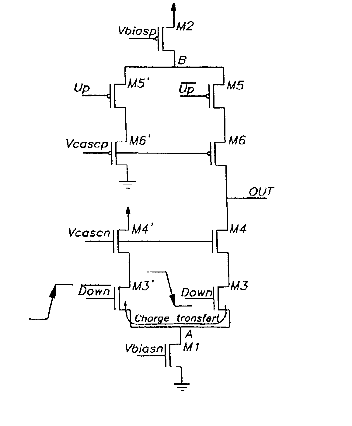
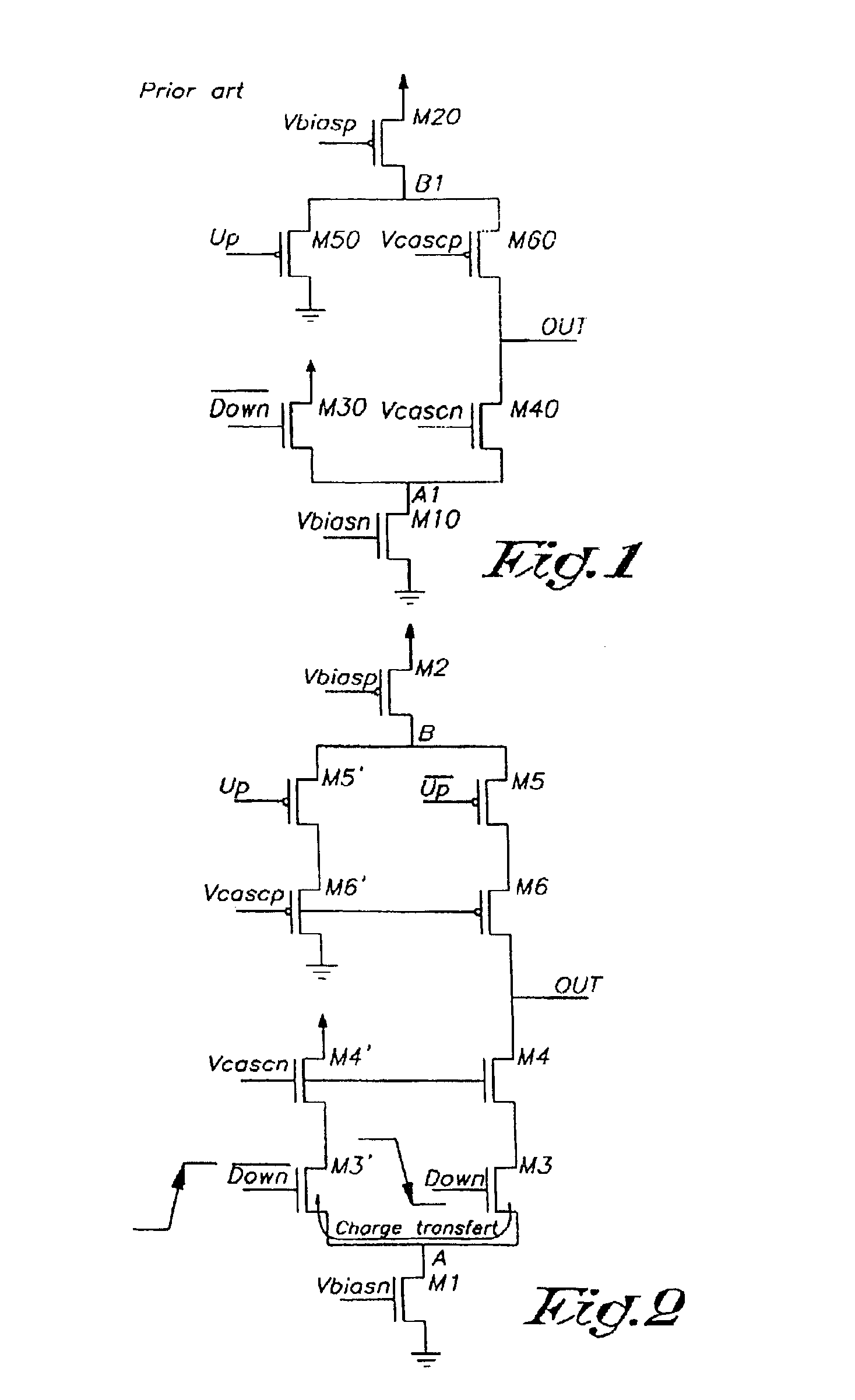
[0015]The charge pump elementary current source cell of FIG. 2, shown as example only, has a specific structure that reduces the artifacts of the charge injections and clock feedthrough. This improves the phase noise of the phase locked loop (PLL) where this charge pump structure is used. Simulations and measurements demonstrate the effective benefit of this structure.

[0016]The charge injection and the clock feedthrough are effectively reduced by the use of a specific switched cascode structure shown in FIG. 2.

[0017]The cell of FIG. 2 comprises:[0018]a drain node A with a current source transistor M1,[0019]a drain node B with a current source transistor M2,[0020]a branch connecting the node A to the node B, said branch comprising a first cascode transistor M4 and a second cascode transistor M6, a first intermediate switch transistor M3 being placed between the cascode transistor M4 and the current source transistor M1, while a second intermediate switch transistor M5 is placed betwe...


PUM


Abstract

Phase locked loop charge pump comprising a drain node (A, B) and at least a cascode transistor (M4, M6) for limiting the variation of the voltage of said drain node, characterized in that an intermediate switch transistor (M3, M5) is placed between the drain node (A, B) and the cascode transistor (M4, M6).

Description

BACKGROUND OF THE INVENTION[0001]The present invention relates to a low spurious charge pump for low phase noise phase locked loops (PLL). Such a charge pump can be used in analog PLL design, solid state circuits, ASIC, integrated circuits, etc.[0002]IEEE paper “A 1.4 gHz Differential Low noise CMOS Frequency Synthesiser using a wideband PLL architecture” from the authors Li Lin et al. published at the 2000 IEEE International Solid State Circuits conference describes PLL charge pumps which are built around a simple cascoded current source. Such a PLL charge pump is schematically shown in appended FIG. 1. Any variation of the voltage of the drain node A1 or B1 of the current source transistor M10 or M20 due to a variation of the output voltage is limited by the cascode transistor M40 or M60. A switch transistor M30, M50 placed in parallel with a cascode transistor, respectively M40, M60 is deviating or not the current pumped by M10 or injected by M20 according to the control signal.[...

Claims


Application Information

Patent Timeline
IPC IPC(8): H03L7/089H03L7/08
CPCH03L7/0896
Inventor DELMOT, THIERRYBONJEAN, FRANS THERESIA JOZEF
Owner ALCATEL LUCENT SAS
Why Eureka
Try Eureka