
Orthopedic system having detachable bone anchors

a bone anchorage and orthopedic technology, applied in the field of orthopedic system, can solve the problems of increasing the risk of infection for patients, designing the early fixator and distractors, and causing bone to have certain problems

Inactive Publication Date: 2005-04-26
SYNTHES USA
View PDF55 Cites 60 Cited by
  • Summary
  • Abstract
  • Description
  • Claims
  • Application Information

AI Technical Summary

Benefits of technology

[0011]The orthopedic system of the present invention includes at least two bone anchors. Each of these anchors has a bone-contacting surface and fastener-connecting portion. There is a fastener associated with each bone anchor; the fastener includes a device-connecting portion for connection to an orthopedic device (such as a distractor), and an anchor-connecting portion for establishing a releasable mechanical coupling with the fastener-connecting portion of the associated anchor. An orthopedic device, such as a distractor, is coupled to the device-connecting portions of each fastener in order to perform the desired procedure. After the orthopedic procedure involving the orthopedic device is complete, the mechanical couplings of the fasteners to the bone anchors can be released, allowing the fasteners and device to be easily removed from the patient without requiring the removal of the bone anchors.
[0013]The releasable coupling of at least one of the bone anchors and fastener may comprise a detent mechanism. Preferably, the release of the detent mechanism is prevented when the orthopedic device is substantially fully coupled to the device-connecting portion of that fastener; this avoids undesired release of the system while it is in use. Release of the detent mechanism is permitted when the orthopedic device is at least partially uncoupled from the device-connecting portion of that fastener, such that the system can be disassembled when desired.
[0017]The proximal bone plate is also designed to be subcutaneously implanted, and is attached to the second bone section. The proximal bone plate has screw holes adapted to receive bone screws, a bone-contacting surface, and a second engagement cavity. A proximal fastener is provided, to be associated with the proximal bone plate; this proximal fastener has a device-connecting portion and a anchor-connecting portion. The releasable coupling of the proximal bone plate and proximal fastener comprises a detent mechanism. Release of the detent mechanism is prevented when a distraction device is fully coupled to the device-connecting portion of the proximal fastener, but release of the detent mechanism is permitted when the orthopedic device is at least partially uncoupled from the device-connecting portion of the proximal fastener. In use, the distraction device is coupled to the device-connecting portions of each fastener. According to the novel orthopedic system of the present invention, when desired, both fasteners can be released from their corresponding bone plates, allowing the fasteners and distraction device to be easily removed from the patient without requiring the removal of the bone plates.

Problems solved by technology

The design of the early fixators and distractors, which used bone pins and screws to attach the device to the bone are known to have certain problems.
Each pin involves a transcutaneous incision, thus multiplying the risk of infection to the patient.
Furthermore, a pin clamp or coupling is required to join the fixation / distraction mechanism to the pins, and the design and operation of these couplings are complicated by the difficulty in aligning the pins accurately when they are inserted into the bone.
Finally, because the pins extend in a generally perpendicular direction from the insertion site, they cause the resultant overall device to stick out quite far from the patient's body (i.e., the device has a high profile), and the device is unsightly.
However, modem low-profile fixation / distraction systems such as that disclosed in the Robinson patent suffer from the drawback that their use necessitates two substantial, invasive, surgical procedures: one to implant the device, and another to remove it after the fixation / distraction procedure is complete.
Unnecessary surgical procedures are of course undesirable, based on both considerations of health care costs and the medical risks associated with surgery.

Method used


Image

  • Orthopedic system having detachable bone anchors
  • Orthopedic system having detachable bone anchors
  • Orthopedic system having detachable bone anchors

Examples


Embodiment Construction

[0032]The orthopedic device of the present invention is discussed herein with reference to a preferred embodiment adapted to be used in a linear distraction of a mandible. However, it will be clear that the invention is not limited to mandibular distraction, or indeed to distraction generally, but rather finds general application for use with any orthopedic device that involves anchoring devices to bone.

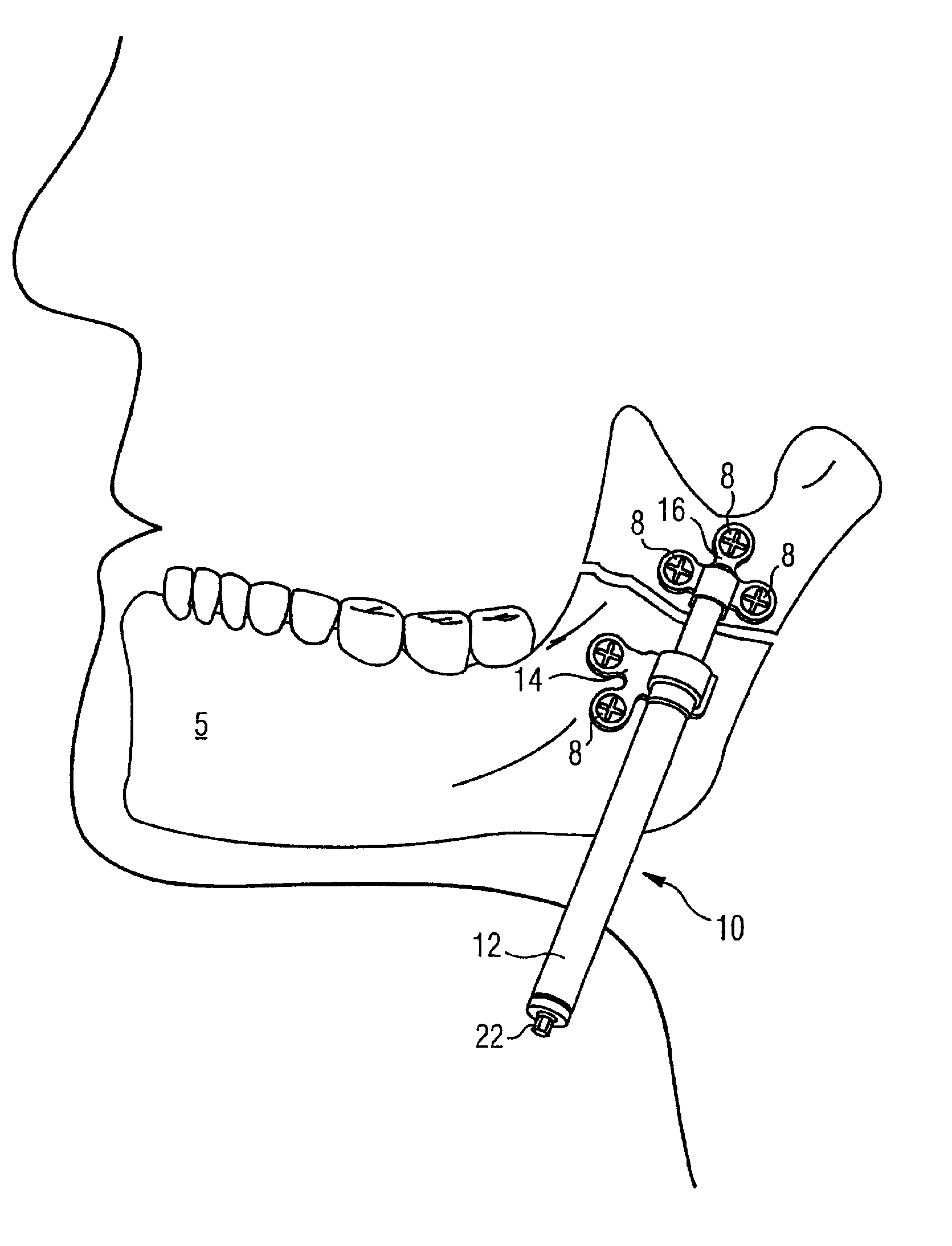
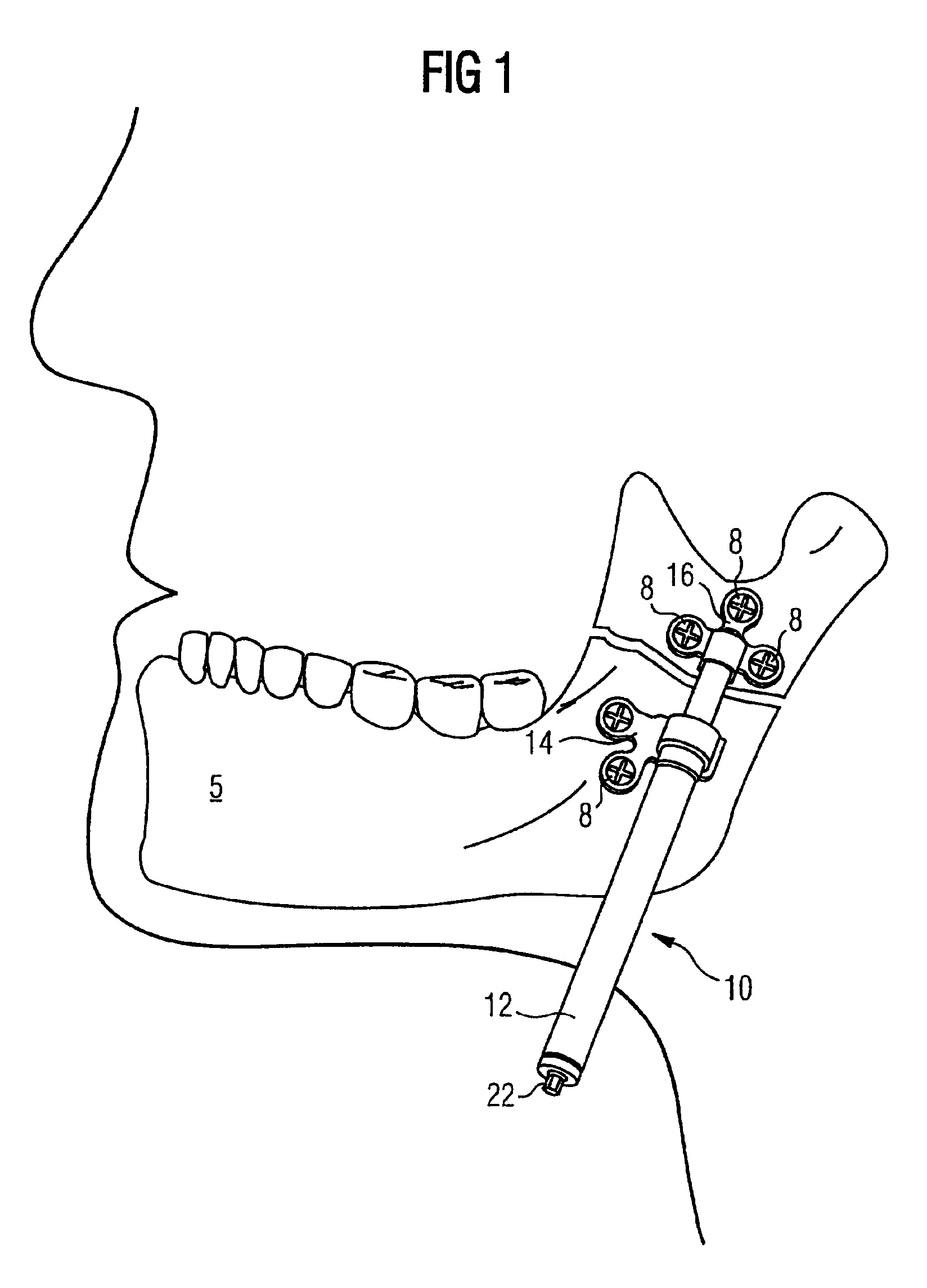
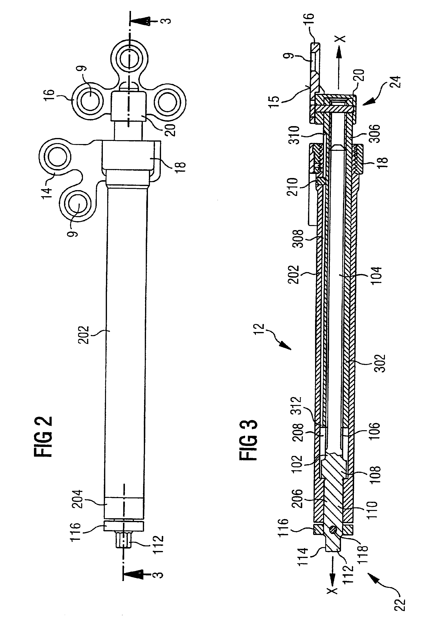
[0033]As seen in FIGS. 1-3, the orthopedic system 10 generally consists of distraction assembly 12, proximal and distal foot plates (or bone plates) 14 and 16, respectively, and proximal and distal fasteners 18 and 20, respectively. The distraction assembly 12 has a proximal, or adjustment end 22, and a distal end 24. The orthopedic system 10 is affixed to mandible 5 by bone screws 8 which are inserted through screw-holes in foot plates 14 and 16. In use, the entire orthopedic system 10 is implanted subcutaneously, except for the adjustment end 22 of the distraction assembly 12, whic...


PUM


Abstract

The present invention provides an improved orthopedic system in which the part of a device that attaches to the bone is detachable from the rest of the device. The system includes a proximal bone anchor, associated proximal fastener, a distal bone anchor, and associated distal fastener. The bone anchors are affixed to the bone on opposing sides of the bone repair site, which may be an osteotomy. The fasteners serve to releasably mechanically couple the orthopedic device, which may be a distractor, to the bone anchors. In a preferred embodiment, the bone anchors are made from a resorbable material.

Description

[0001]The present application is a continuation of the U.S. patent application Ser. No. 09 / 274,698, filed on Mar. 23, 1999 now U.S. Pat. No. 6,423,069.TECHNICAL FIELD[0002]The present invention relates to an orthopedic system and, more particularly, to an improved orthopedic system wherein the part of the device that attaches to the bone is detachable from the parts of the system which provide the bone fixation, reduction, distraction, etc.BACKGROUND OF THE INVENTION[0003]A variety of orthopedic devices, including bone fixation, reduction, and distraction devices, are known in the art. Fixation devices, or fixators, are used to stabilize bone segments and to facilitate the healing of bones at a bone repair site. As used herein “bone repair site” refers to any bone region which is bounded on opposing sides by relatively healthy bone regions to which orthopedic devices can be secured, such as an osteotomy or a fracture. Reduction and distraction devices (commonly referred to as reduce...

Claims


Application Information

Patent Timeline
Patent Type & Authority Patents(United States)
IPC IPC(8): A61B17/60A61B17/66A61B17/86A61B17/80A61B17/68A61B17/00A61B17/58
CPCA61B17/663A61B17/8071Y10S606/904A61B2017/00004Y10S606/908A61B17/866
Inventor SELLERS, TIMOTHY M.
Owner SYNTHES USA
Learn More