Monotonic up-counter in an integrated circuit
a counter and integrated circuit technology, applied in pulse counters, computation using non-denominational number representations, instruments, etc., can solve problems such as incompatibility of destructive programming and programming with programming
- Summary
- Abstract
- Description
- Claims
- Application Information
AI Technical Summary
Benefits of technology
Problems solved by technology
Method used
Image
Examples
second embodiment
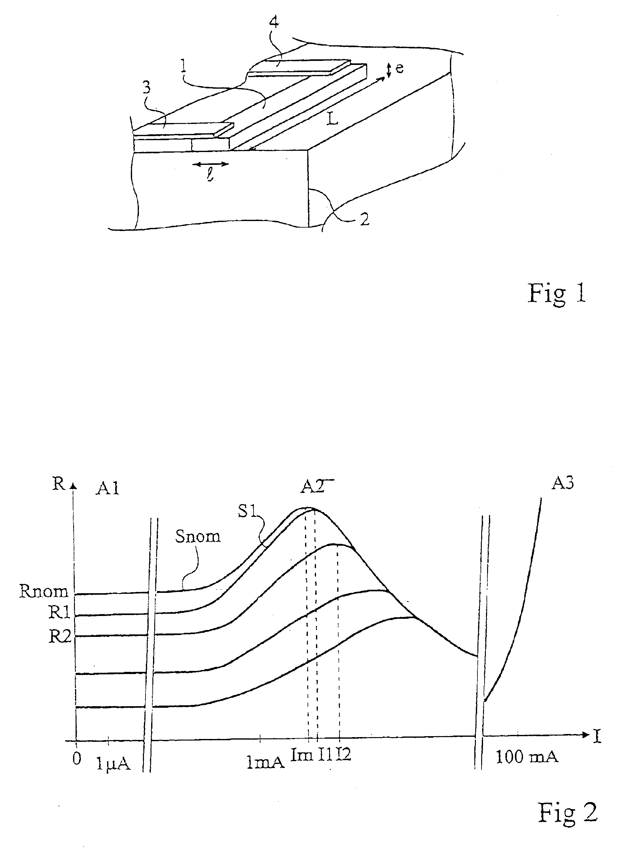
[0053]According to another preferred example, the different currents to be applied to pass from the different resistance values to smaller values are predetermined, for example, by measurements. This predetermination takes of course into account the nature of the polysilicon used as well as, preferentially, the square resistance, that is, the resistivity of the material and the thickness with which it is deposited. Indeed, since the curves illustrated by FIG. 2 may also be read as the curves of the square resistance, the calculated values may be transposed to the different resistors of an integrated circuit defined by widths and the lengths of the resistive sections. According to this second embodiment, the value of the constraint current to be applied to the resistive element to decrease its value in an irreversible and stable manner can then be predetermined.
[0054]The curve change, that is, the decrease in the resistance value in normal operation is almost immediate as soon as the...
first embodiment
[0055]FIG. 3 shows a one-time programming counting cell (or memory cell) according to the present invention.
[0056]Cell 11 comprises, in series with a first terminal 12 of application of a positive supply voltage and a second terminal 13 of application of a more negative or reference supply voltage V− (generally, the ground), a resistor Rp programmable by irreversible decrease in its value such as described hereabove in relation with FIGS. 1 and 2, and a programming switch, here, an N-channel MOS transistor (MN) Resistor Rp forms the storage element of cell 11. The state stored in the cell is read from junction point 14 of resistor Rp with transistor MN. The reading of the stored level is performed by comparison with a reference level.
[0057]To enable reading of the state stored in cell 11, a resistor Rb (shown in dotted lines in FIG. 3) is provided, which, when transistor MN is off, forms with resistor Rp a voltage-dividing bridge. Resistor Rb has been shown in dotted lines to illust...
third embodiment
[0064]FIG. 5 shows a cell 11″ of irreversible counting according to the present invention. The essential difference with respect to the counting cells shown in FIGS. 3 and 4 is that the structure of FIG. 5 is a differential structure which does not use a reference voltage to perform the comparison enabling detecting the state stored in the cell.
[0065]Cell 11″ of FIG. 5 comprises two resistive branches in parallel between two supply terminals 12 and 13, two programming transistors MN1 and MN2 (in this example, N-channel MOS transistors), a control circuit 25 (CTRL), and a selector K between two supply voltages, respectively of reading Vr and programming Vp. The programming of a cell such as illustrated in FIG. 5 occurs similarly to that of the cells of FIGS. 3 and 4. What here changes is the cell structure enabling the reading.
[0066]In the embodiment of FIG. 5, a first so-called left-hand branch in the orientation of the drawing comprises in series a first resistor Rp1, a read MOS tr...
PUM
 Abstract
Description
Claims
Application Information
 - R&D
- Intellectual Property
- Life Sciences
- Materials
- Tech Scout
- Unparalleled Data Quality
- Higher Quality Content
- 60% Fewer Hallucinations
Browse by: Latest US Patents, China's latest patents, Technical Efficacy Thesaurus, Application Domain, Technology Topic, Popular Technical Reports.
© 2025 PatSnap. All rights reserved.Legal|Privacy policy|Modern Slavery Act Transparency Statement|Sitemap|About US| Contact US: help@patsnap.com


