
Conductive tubular insert for a fuel transport system, and method

Inactive Publication Date: 2005-04-19
FLUID ROUTING SOLUTIONS
View PDF16 Cites 13 Cited by
  • Summary
  • Abstract
  • Description
  • Claims
  • Application Information

AI Technical Summary

Benefits of technology

[0005]It is another object of the invention to provide connecting means for connecting the plastic fuel tube having an inner electrical conductive layer, to a rubber hose having an inner electrical conductive layer, wherein continuity of the electrical conductivity is maintained while preserving the fuel impermeability of the plastic tubular member.
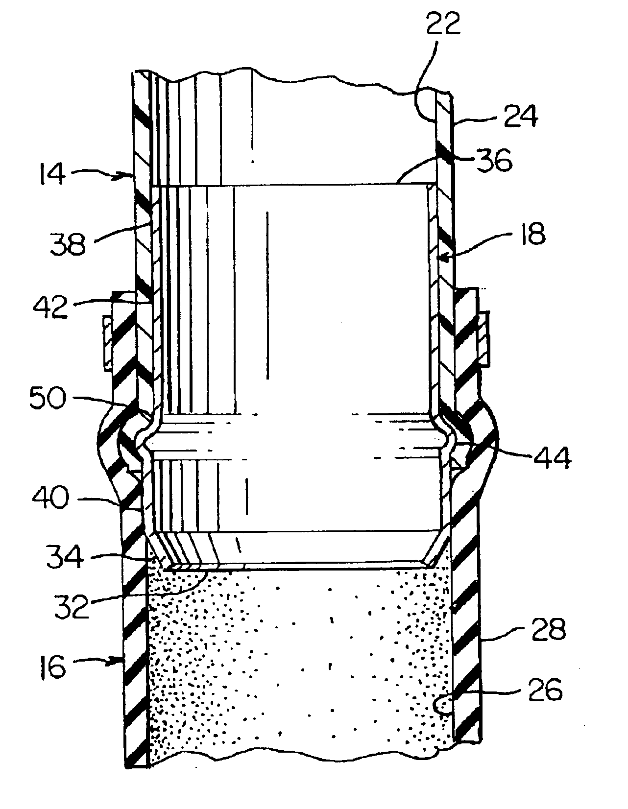
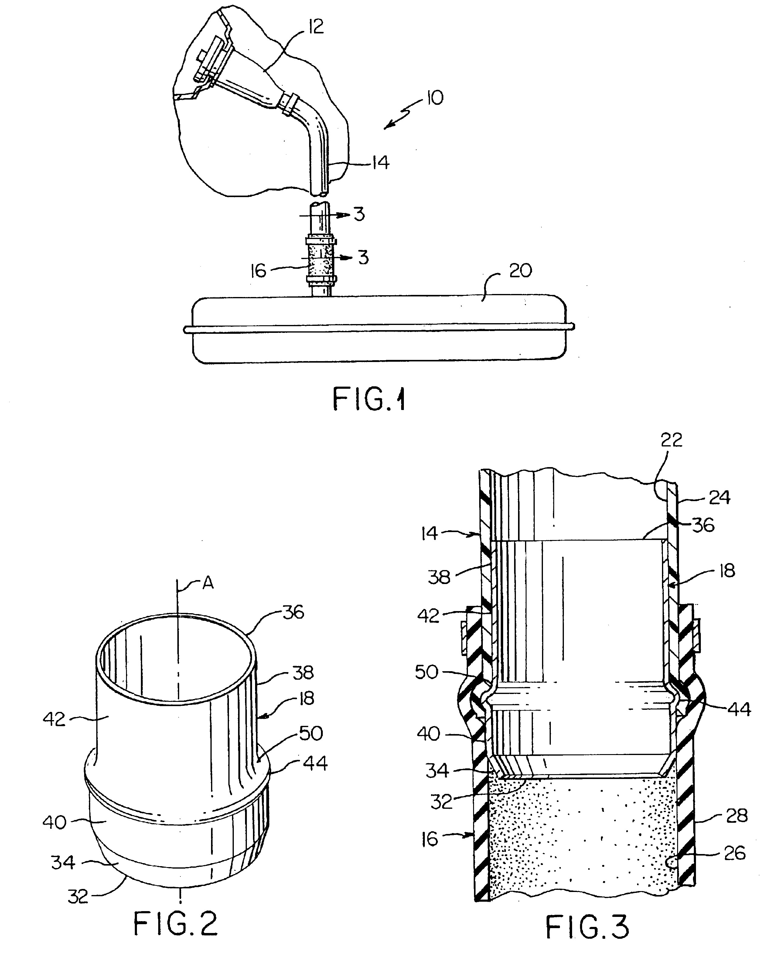
[0008]According to the invention, a polymeric tubular fuel transport member having an electrically conductive inner layer is installed between the fuel intake funnel of an automotive vehicle and one end of a polymeric hose having an electrically conductive inner surface, the other end of the polymeric hose being secured to the fuel tank. An electrically conductive insert connector is employed to connect the polymeric tubular fuel transport member to the polymeric hose so that electrical continuity is maintained between the fuel transport hose and the polymeric hose. In a preferred aspect of the invention, one end of the conductive insert connector is inserted into an open end of the plastic tubular member such that the other end of the electrically conductive insert connector extends outward beyond the open end of the fuel transport tubular member. The polymeric hose which preferably has an inner diameter equal to or slightly larger than the outer circumference of the polymeric tubular fuel transport member is forced over the other end of the conductive insert connector and then over the end of the polymeric tubular fuel transport member having the conductive insert connector therein, such that the extended portion of the electrically conductive insert connector is in intimate contact with both the inner conductive layer of the polymeric tubular fuel transport member and the inner conductive layer of the polymeric hose, thereby providing continuity of the electrical conductivity between the plastic tubular member and the rubber hose while, at the same time, allowing the connection between the polymeric tubular fuel transport member and the polymeric hose to be securely effected by securing means, e.g., clamping means, such as a spring clamp or screw clamp, to prevent pull-off. By way of the present invention, the continuity of the required electrical conductivity in the fuel filler system between the entrance of the fuel into the polymeric fuel transport tubular member and the polymeric hose, and the exit of the fuel into the fuel tank is maintained.
[0009]The electrically conductive insert connector may be manufactured from any material which possesses the necessary electrical conductivity. Typically, the electrically conductive insert connector is made from metal or a plastic material which has electrical conductivity throughout, from the inner most layer to the outer most layer. More specifically, the conductive connector insert of the present invention has a robust tubular shape wherein the connector is configured to allow the connector insert to seat in the tube member to form a bead which prevents leaking as well as providing improved pull-off forces.

Problems solved by technology

Since the tubular structure transporting the fuel is required to have a high degree of fuel impermeability as well as being electrically conductive, it is difficult to provide a plastic tube which is made solely of an electrical conductive resin.

Method used


Image

  • Conductive tubular insert for a fuel transport system, and method
  • Conductive tubular insert for a fuel transport system, and method
  • Conductive tubular insert for a fuel transport system, and method

Examples


Embodiment Construction

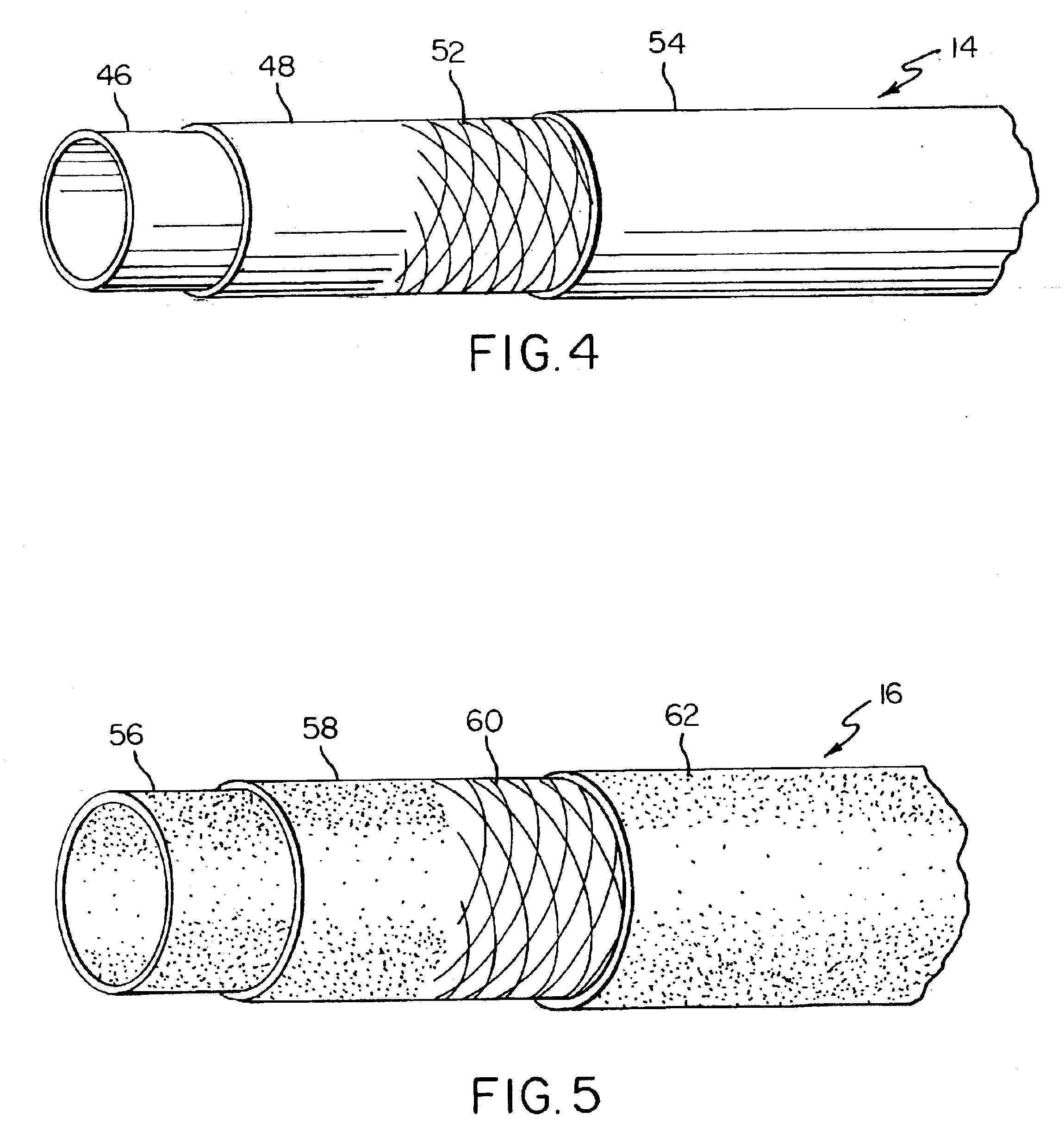
[0015]Referring to the drawings, FIG. 1 illustrates one aspect of the invention where a fuel fill tube assembly 10 includes a fuel funnel 12, a first polymeric tubular member 14 which is preferably a thermoplastic material, a second polymeric tubular member 16 which is preferably a rubber material, a conductive connector insert 18 (FIG. 3) connecting the first polymeric tubular member 14 to the second polymeric tubular member 16, and a fuel tank 20. The first polymeric tubular member 14, hereinafter referred to as a plastic or thermoplastic member, includes at least a conductive inner surface 22 and a non-conductive outer surface 24, and the second polymeric tubular member 16, hereinafter referred to as a rubber member, includes at least a conductive inner surface 26 and a non-conductive outer surface 28. In accordance with the invention, the plastic tubular member 14 and the rubber tubular member 16 are connected to each other by the conductive connector 18 such that conductive con...


PUM

PropertyMeasurementUnit
Pressureaaaaaaaaaa
Electrical conductoraaaaaaaaaa
Circumferenceaaaaaaaaaa

Abstract

A conductive tubular connector insert for use in a fuel conveying system to couple a first conductive polymeric tubular member to a second conductive polymeric tubular member such that electrical conductivity is insured in the system as described. The conductive tubular connector comprises: a first end having a first annular margin; a second end having a second annular margin; a first tubular body section having a first circumference; a second tubular body section having a second circumference; and an annular rib, wherein the first tubular body section is adjacent the first end and extends toward the annular rib along a longitudinal axis, and the second tubular body section extends from the annular rib toward the second end where, at a point intermediate the circumferential rib and the second end, the second tubular body section tapers radially inward forming a tapered surface terminating in a second annular margin adjacent the second end of the second tubular body section, the configuration of the conductive connector insert being such that, upon being implanted into an end of the first polymeric tubular member, the end of the first polymeric tubular structure forms a bead around the annular rib to secure the conductive connector insert therein leaving a portion of the second tubular body section extending out of the end of the first polymeric tubular member, wherein the end of the first polymeric tubular structure having the second tubular body section extending therefrom is inserted into an end of a second polymeric tubular member such that the conductive connector insert is in conductive contact with the conductive inner surface of the first polymeric tubular member and the conductive inner surface of the second polymeric tubular member to maintain conductive continuity therein.

Description

BACKGROUND OF THE INVENTION[0001]The present invention relates generally to coupling means for connecting plastic tubing to the open end of a hose. More particularly, the invention relates to conductive tube insert for coupling a plastic tubular member having a conductive inner layer to a rubber hose having a conductive inner layer such that conductive continuity is maintained between the conductive inner layer of the plastic tubular member and the conductive inner layer of the rubber hose.[0002]Hose assemblies for transporting various fluids in vehicles, machinery, etc. are known. For installing a fuel transport tube, for example, between the metal funnel and the fuel tank in an automotive vehicle, a metal tubular member is connected to the fuel tank by means of a rubber hose which has a conductive inner surface so that there is conductive continuity in the entire fuel filler line to avoid the generation of static electricity due to the flow of fuel through the fuel filler tube. Of...

Claims


Application Information

Patent Timeline
IPC IPC(8): F16L25/00F16L11/12F16L25/01F16L11/127
CPCF16L11/127F16L25/01B60K2015/047B60K2015/03401B60K15/04F16L2011/047
Inventor MOBLEY, JOHN E.SMITH, CHRISTOPHER W.BUTLER, JAY T.SHIFMAN, JERRY
Owner FLUID ROUTING SOLUTIONS
Learn More